Power tool with spindle lock

A technology of electric tools and shaft components, which is applied in the direction of manufacturing tools, manual planing, passing components, etc., and can solve problems such as crushing injuries, user's finger pressing pain, pinch pain, etc.

Inactive Publication Date: 2009-07-22
BLACK & DECKER INC
View PDF3 Cites 3 Cited by
  • Summary
  • Abstract
  • Description
  • Claims
  • Application Information

AI Technical Summary

Problems solved by technology

Therefore, this process is inconvenient and time consuming
[0007] Additionally, some conventional spindle lock assemblies include buttons that are difficult to press
For example, the button may be relatively small and the bias force require...

Method used


Image

  • Power tool with spindle lock
  • Power tool with spindle lock
  • Power tool with spindle lock

Examples


Embodiment Construction

[0018] The following description is merely exemplary in nature and is not intended to limit the disclosure, application or uses of the invention. Through the drawings, it should be understood that corresponding reference numerals indicate the same or corresponding components and technical features.

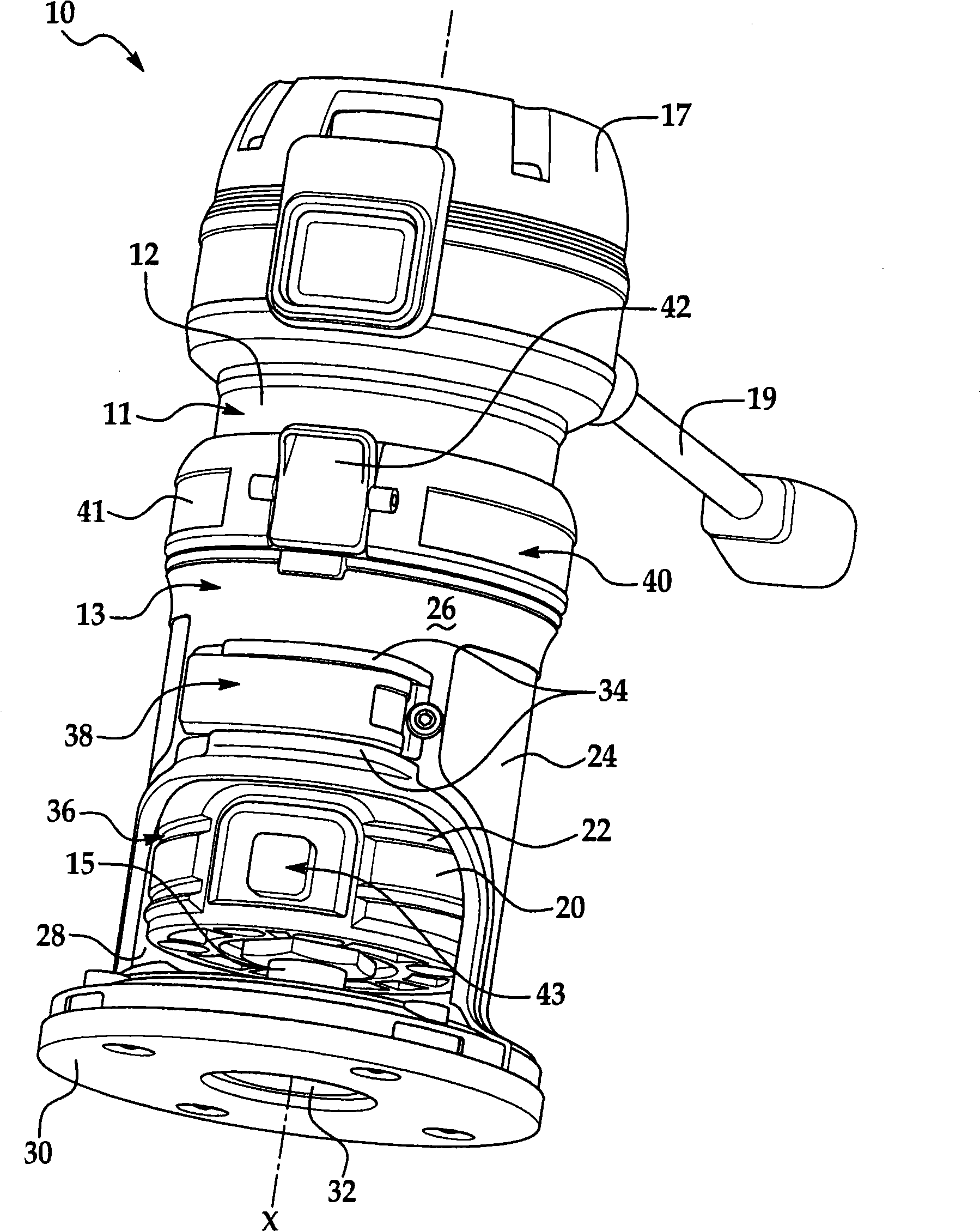
[0019] see first figure 1 , illustrates a power tool 10 . In the illustrated embodiment the power tool 10 is a router; however, the power tool 10 may be any suitable type of power tool without departing from the scope of the present disclosure. It should also be appreciated that certain components of power tool 10 (eg, handles, etc.) have not been shown for purposes of clarity.

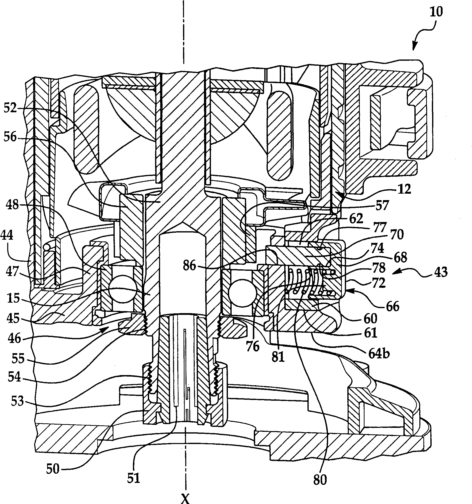
[0020] As shown in the figure, the power tool 10 mainly includes a motor assembly 11 and a base assembly 13 . The motor assembly 11 mainly includes a cylindrical motor housing 12 . Motor housing 12 encloses and supports an electric motor (not shown), which may be of any suitable form. A spindle assem...


PUM


Abstract

The invention discloses a power tool including a spindle assembly supported for rotation about an axis. The spindle assembly includes a plurality of engagement members, and at least two of the engagement members are disposed in spaced relationship less than one hundred eighty degrees from each other with respect to the axis of the spindle assembly. The power tool also includes the spindle lock assembly that selectively engages at least one of the plurality of engagement members to lock the spindle assembly against rotation about the axis.

Description

technical field [0001] The present invention relates to an electric tool, in particular to an electric tool with a spindle locking assembly. Background technique [0002] The descriptions in this part merely provide background information related to the present invention and may not constitute prior art. [0003] Many power tools include an arbor to which the tool can be attached. For example, many routers include an arbor that is removably connected to a collet nut that is used to connect a router bit to the arbor. A motor drives to turn the mandrel and attached router bit. Typically, a collet nut is threaded onto the arbor and is rotatable relative to the arbor in order to connect and disconnect the router bit. Accordingly, many routers include a spindle lock assembly for locking the spindle against rotation so that the collet nut may rotate relative to the spindle. [0004] For example, spindle lock assemblies typically include buttons attached to pins. The buttons a...

Claims


Application Information

Patent Timeline
IPC IPC(8): B25F5/00B27C1/10
CPCB24B23/022B25F5/001Y10S408/71Y10T74/20636Y10T279/3437Y10T279/17538Y10T409/306608Y10T279/3451
Inventor 克雷格·A·卡罗尔丹尼尔·P·沃尔
Owner BLACK & DECKER INC
Why Eureka
Try Eureka