
Video image rotating system

A technology of video image and analog video, applied in the parts of TV system, image communication, TV, etc., can solve the problem of inability to meet the viewing needs and other problems

Active Publication Date: 2010-12-15
FUJIAN XINGHAI COMM TECH
View PDF6 Cites 0 Cited by
  • Summary
  • Abstract
  • Description
  • Claims
  • Application Information

AI Technical Summary

Problems solved by technology

When the display rotates clockwise or counterclockwise, if the input image signal still follows the original data flow, that is, remains unchanged, then what we see is an image rotated 90° clockwise or counterclockwise, which is unable to meet viewing needs

Method used


Image

  • Video image rotating system
  • Video image rotating system
  • Video image rotating system

Examples


Embodiment Construction

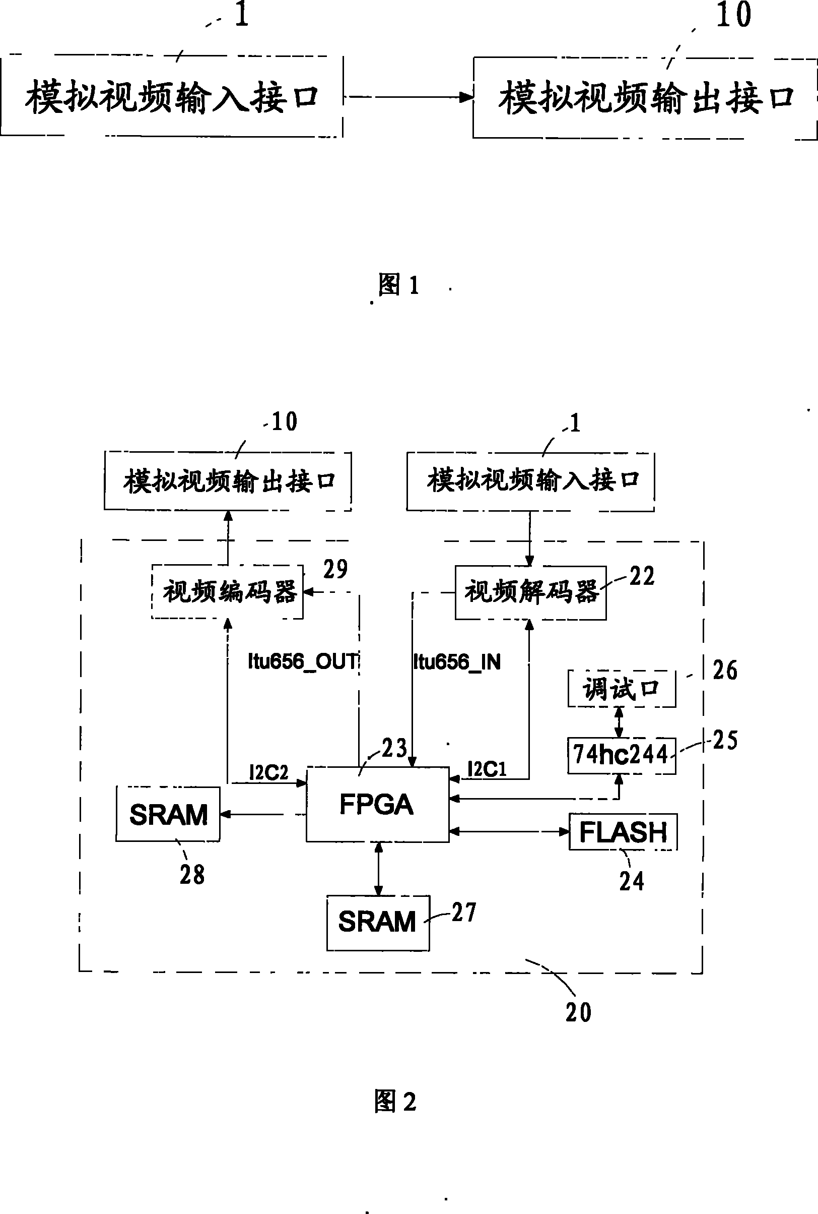
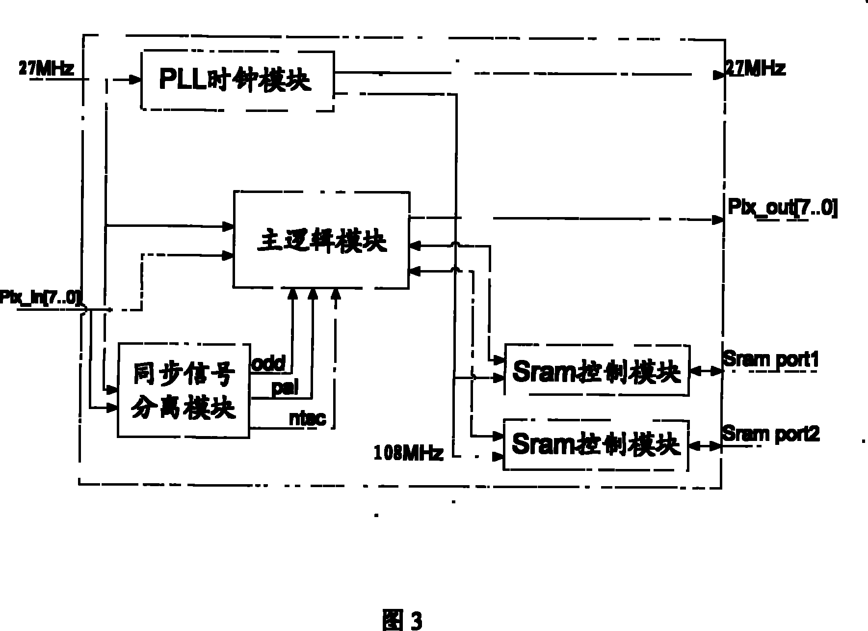
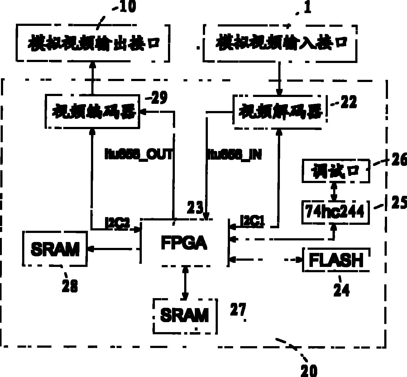
[0021] see figure 1 , is a hardware connection diagram of the video image rotation system of the present invention, and an image processing device 20 is inserted between the original analog video input interface 1 and the analog video output interface 10 . Image processing device 20 includes video decoder 22, FPGA (Field Programmable Gate Array) chip 23, flash memory (FLASH) 24, data buffer chip 25, debugging port 26, first static memory (SRAM) 27, second static memory 28 , and video encoder 29.

[0022] The original video input signal is connected to the analog video input interface 1, and the video signal output by the analog video output interface 10 is connected to the display device. The analog video input interface 1 is connected to the FPGA chip 23 through the video decoder 22, and the FPGA chip 23 passes through Video encoder 29 is connected to analog video output interface 10, and wherein FPGA chip 23 controls video decoder 22 and video encoder 29 respectively by I2C...


PUM


Abstract

A video image rotating system includes an analog video input interface and an analog video output interface, and an image processing device connecting the analog video input interface and the analog video output interface. An original video input signal is accessed to the analog video input interface. A video signal output from the analog video output interface is accessed to a display device. The input analog video signal is transferred by the image processing device to a standard ITU-656 digital video signal, stored in an outer static memory through some transformation logic, read by the outer static memory according to a certain order, and converted to an orthogonal rotated standard ITU-656 digital video signal after passing a main chip and stacking a synchronizing signal of the digital video, finally output after a video coder converts the signal to the analog video signal. The invention has advantages that the system of the invention effectively expands the display application ofthe existing graphic display, employs the prior display at the market without customizing a special purpose display to satisfy a specified environment and a specified application demand.

Description

【Technical field】 [0001] The invention relates to a display device or a method for displaying signals, in particular to a video image rotation system. 【Background technique】 [0002] FPGA (Field Programmable Gate Array) is a field programmable gate array, which emerged as a semi-custom circuit in the field of application-specific integrated circuits (ASIC). The disadvantage of limited number of circuits. The use of FPGA is very flexible, and the same FPGA can generate different circuit functions through different programming data. FPGA has been widely used in many fields such as communication, data processing, network, instrument, industrial control, military and aerospace. [0003] Such as figure 1 As shown, the existing internal data flow of the image displayed on the display is directly input from the analog video input interface 1 to the analog video output interface 10 . In some special application fields, sometimes in order to obtain better display effect, it is ne...

Claims


Application Information

Patent Timeline
Patent Type & Authority Patents(China)
IPC IPC(8): G09G5/373G09G5/00H04N7/01H04N5/44
Inventor 李祺
Owner FUJIAN XINGHAI COMM TECH
Learn More