Ink ribbon cassette

A technology for ink ribbon cassettes and ink ribbons, applied in the directions of ink ribbon cassettes, inking devices, printing, etc., can solve the problems of assembling the ink ribbon cassettes and other problems.

Inactive Publication Date: 2009-07-22
DAI NIPPON PRINTING CO LTD
View PDF4 Cites 2 Cited by
  • Summary
  • Abstract
  • Description
  • Claims
  • Application Information

AI Technical Summary

Problems solved by technology

Therefore, if there is a protruding part on the surface of the ink ribbon cassette, it may become an obstacle when the ink ribbon cassette is assembled at a predetermined position in the printing machine.

Method used


Image

  • Ink ribbon cassette
  • Ink ribbon cassette
  • Ink ribbon cassette

Examples


no. 1 approach

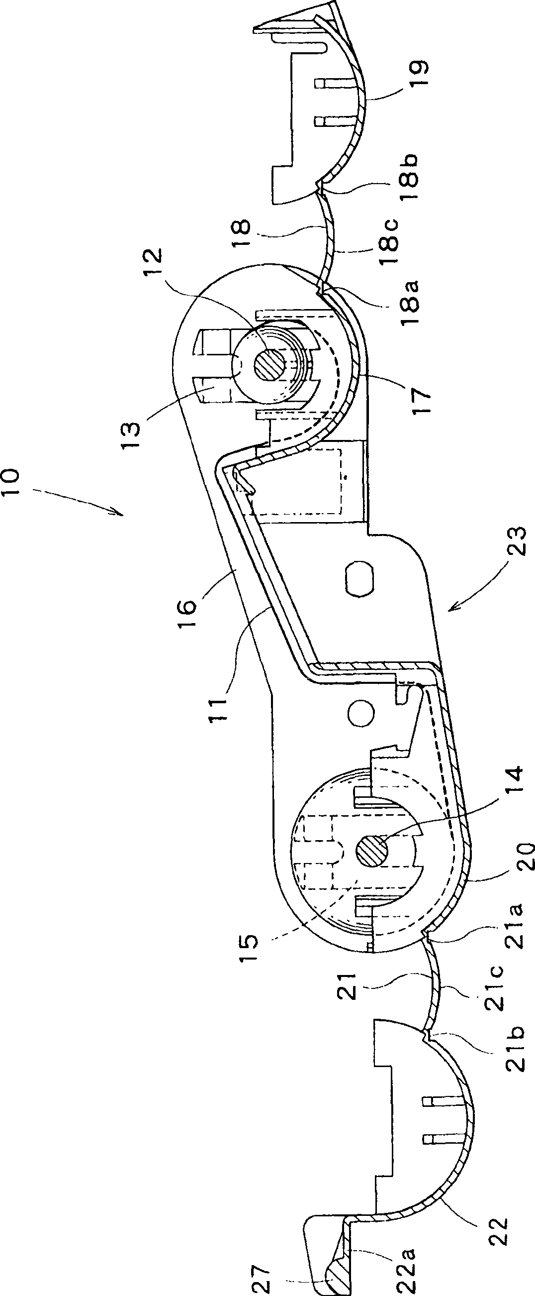
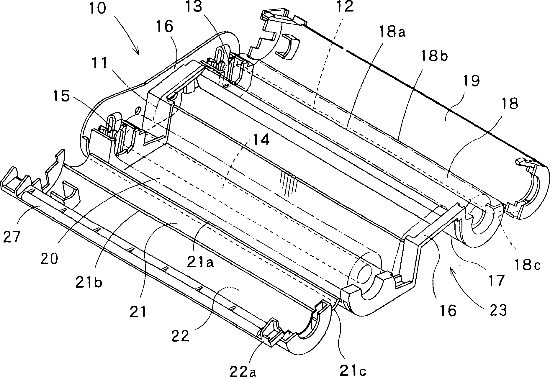
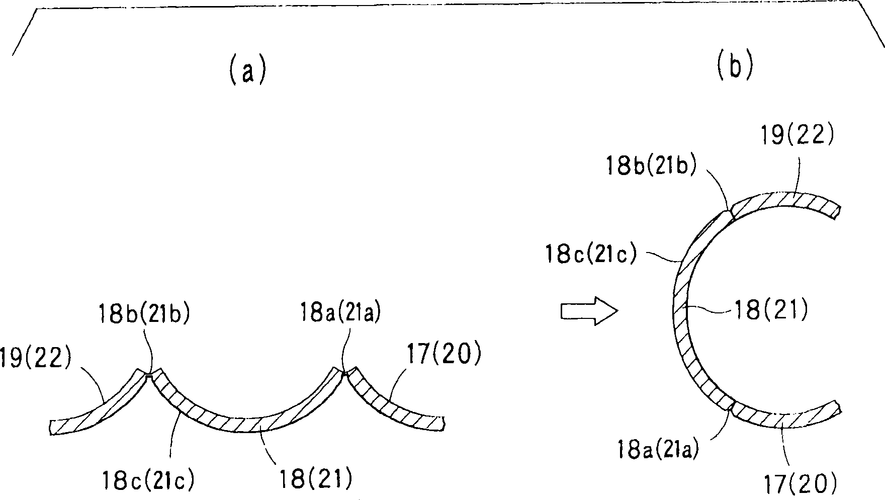
[0047] here, figure 1 Is a cross-sectional view showing the first embodiment of the present invention, figure 2 It is a perspective view showing the first embodiment of the present invention. In addition, image 3 (a) is a cross-sectional view showing a state where the winding bearing cover member (winding bearing cover member) of the bearing device is opened relative to the winding bearing body (winding bearing body), image 3 (b) is a cross-sectional view showing a state where the winding bearing cover member (winding bearing cover member) of the bearing device is closed with respect to the winding bearing body (winding bearing body). In addition Figure 4 It is a partial cross-sectional view of the winding bearing body in a state where the winding bearing cover member is closed with respect to the winding bearing body. In addition Figure 5 Is a cross-sectional view showing a modification of the first embodiment of the ink ribbon cassette of the present invention, Figure 6 I...

no. 2 approach

[0084] Next, refer to Figure 7 as well as Figure 8 The second embodiment of the present invention will be described.

[0085] here, Figure 7 Is a perspective view showing the second embodiment of the present invention, Figure 8 It is a figure which shows the guide rod of the bearing device of the ink ribbon cassette of the 2nd Embodiment of this invention. Figure 7 as well as Figure 8 The installation position of the guide rod 25 in the second embodiment shown is different, and the other structure is substantially the same as the first embodiment described above. in Figure 7 as well as Figure 8 Middle, right and Figure 1 to Figure 6 The same parts in the first embodiment shown are denoted by the same reference numerals and detailed descriptions are omitted.

[0086] Such as Figure 7 As shown, the bearing device 23 of the ink ribbon cassette 10 has a guide rod 25 that is fixed on the winding bearing body 20 and abuts the ink ribbon 11 and guides the ink ribbon 11. The gui...


PUM


Abstract

An ink ribbon cassette (10) is provided with a shaft container (23) including a reel-out shaft holder (17) having a reel-out shaft bearing (13) journaling an ink ribbon reel-out shaft (12); a reel-in shaft holder (20) having a reel-in shaft bearing (15) journaling an ink ribbon reel-in shaft (14); and a pair of lateral bodies (16) connecting the reel-out shaft holder (17) to the reel-in shaft holder (20). A reel-out shaft holder cover (19) adapted to cover the reel-out shaft holder (17) of the shaft container (23) is connected to the reel-out shaft holder (17) via a first connecting body (18). A reel-in shaft holder cover (22) adapted to cover the reel-in shaft holder (20) of the shaft container (23) is connected to the reel-in shaft holder (20) via a second connecting body (21). The first and second connecting bodies (18) and (21) have two or more hinges (18a, 18b); and (21a, 21b), respectively.

Description

Technical field [0001] The present invention relates to a thermal transfer ink ribbon cartridge, and particularly relates to a miniaturized ink ribbon cartridge without a hinge part protruding to the outside. Background technique [0002] Generally, an ink ribbon cartridge with a thermal transfer ink ribbon is widely used in printing equipment such as printers. The thermal head of the printer contacts the ink ribbon, and thermally transfers the printed material on the ink ribbon. Printing ink ribbon dyes and pigments. Such a thermal transfer ink ribbon is supplied from the ink ribbon take-up shaft of the take-up bearing body of the ink ribbon cassette during printing, and is taken up by the ink ribbon take-up shaft of the take-up bearing body of the ink ribbon cassette. [0003] That is, as Picture 9 As shown, the conventional ink ribbon cartridge 30 is provided with: a winding bearing body 37 having a winding bearing 31 that axially supports the ink ribbon winding shaft 35 on w...

Claims


Application Information

Patent Timeline
Patent Type & Authority Applications(China)
IPC IPC(8): B41J17/32B41J32/00
CPCB41J17/32B41J32/00
Inventor 松林秀树开田英正泽良裕井本和信小保内直博
Owner DAI NIPPON PRINTING CO LTD
Why Eureka
Try Eureka