
Current-sensing apparatus and method for current sensing

A technology for compensating current and circuits, applied in the field of current detection devices

Inactive Publication Date: 2009-07-29
SIEMENS AG
View PDF0 Cites 15 Cited by
  • Summary
  • Abstract
  • Description
  • Claims
  • Application Information

AI Technical Summary

Problems solved by technology

[0004] However, the problem with magnetic field measurements with magnetic field sensors is that these magnetic field sensors are sensitive to external and interfering fields

Method used


Image

  • Current-sensing apparatus and method for current sensing

Examples


Embodiment Construction

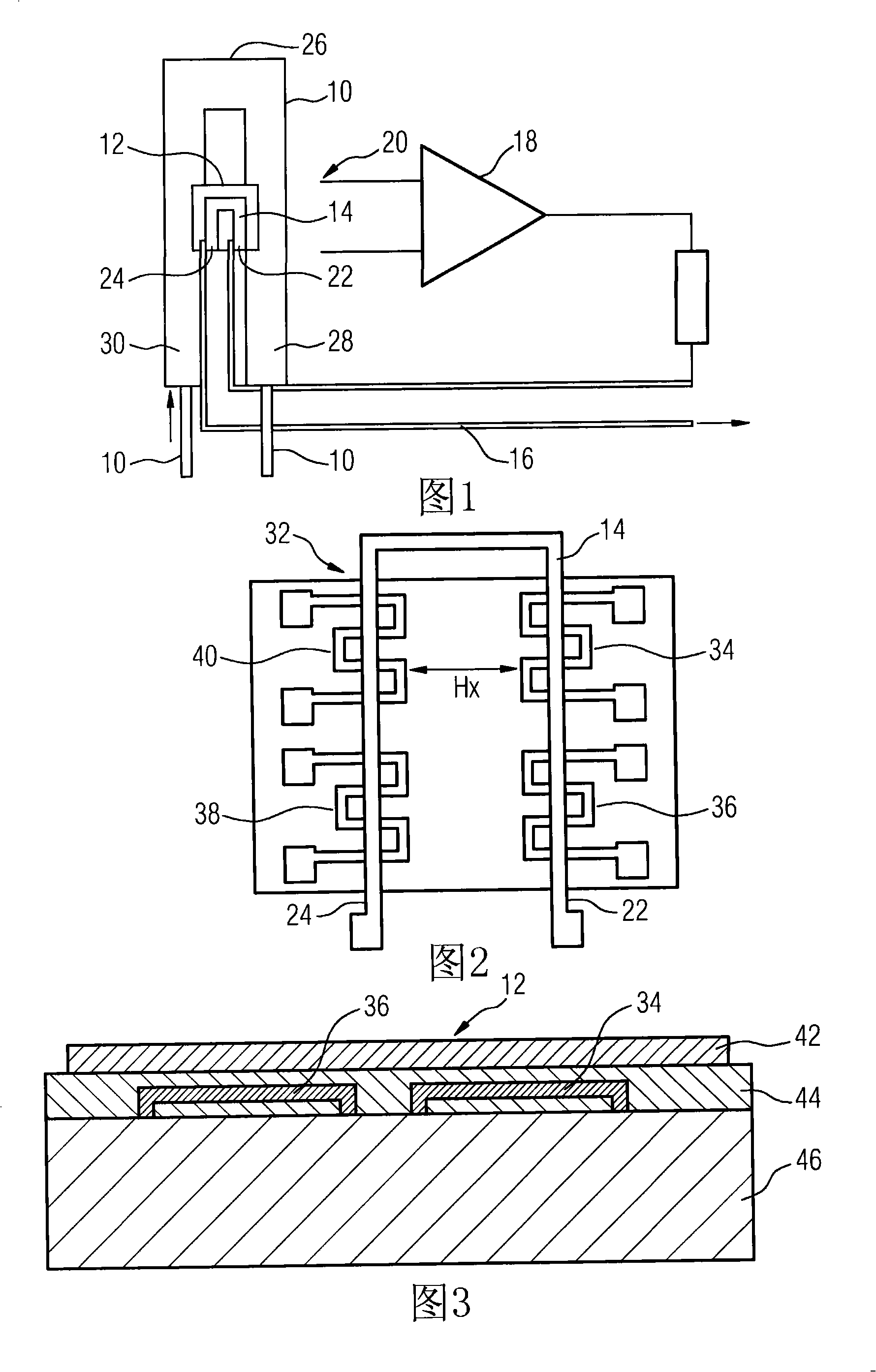
[0026]FIG. 1 illustrates in simplified schematic form an assembly 12 with a GMR sensor acting as a current sensor as means for detecting at least one electrical variable, in particular a circuit 10 (measuring circuit ), wherein the GMR sensor (or component 12 ) includes the conductor segment 14 of the compensation circuit 16 . An amplifier 18 is provided for feeding the compensation current to the compensation circuit 16 , which amplifier receives the signal of the component 12 or the GMR sensor it comprises at least one input 20 . The signal at the input 20 of the amplifier 18 corresponds to the total field strength of the magnetic field generated by the current flowing from the measuring circuit 10 and to the field strength generated by the compensation current flowing through the compensation circuit 16 . When the magnetic field of the measuring circuit 10 is canceled (ie compensated) by the accompanying magnetic field of the compensation current, the signal at the input 20...


PUM


Abstract

The invention specifies a current-sensing apparatus and a method for its operation which is based on the current sensor provided being a GMR sensor in the form of a gradient sensor (32) and on the gradient sensor (32), or a component (12) which comprises this gradient sensor (32), itself comprising a conductor section (14) of a compensating circuit (16), which means that the current in the measurement circuit can be compensated for by a current in the compensating circuit (16) and the compensating current can be evaluated as a measure of the electrical variable to be detected for the measurement circuit (10).

Description

technical field [0001] The invention relates to a current detection device according to the preamble of claim 1 , having a magnetic field sensor as current sensor, which is designed in particular as a GMR sensor. In addition, the invention also relates to a corresponding current detection method. Background technique [0002] Current sensing devices or current sensors are well known in the art. In this regard, for example, known methods for detecting alternating currents are realized by means of inductive current transformers, so-called Hall sensors, and in the case of higher currents, by means of so-called Rogowski coils. The isolation detection of DC is much more complicated. At present, the following methods are mainly used in this regard: the use of shunt resistors in combination with differential amplifiers, electrical isolation (such as realized by optocouplers) and floating power supplies. Alternative methods are based on the use of Hall current measurement systems...

Claims


Application Information

Patent Timeline
IPC IPC(8): G01R15/20
CPCG01R15/205
Inventor 戈塔尔迪·里格尔理查德·施密特罗兰·魏斯
Owner SIEMENS AG
Learn More