Sensor device with alternating excitation fields

A technology of excitation field and magnetic sensor, which is applied in the direction of instruments, scientific instruments, measuring magnetic variables, etc., can solve the problem of sensor accuracy reduction

Inactive Publication Date: 2009-04-01
KONINKLIJKE PHILIPS ELECTRONICS NV
View PDF5 Cites 2 Cited by
  • Summary
  • Abstract
  • Description
  • Claims
  • Application Information

AI Technical Summary

Problems solved by technology

As a result, the accuracy o

Method used


Image

  • Sensor device with alternating excitation fields
  • Sensor device with alternating excitation fields
  • Sensor device with alternating excitation fields

Examples


Embodiment Construction

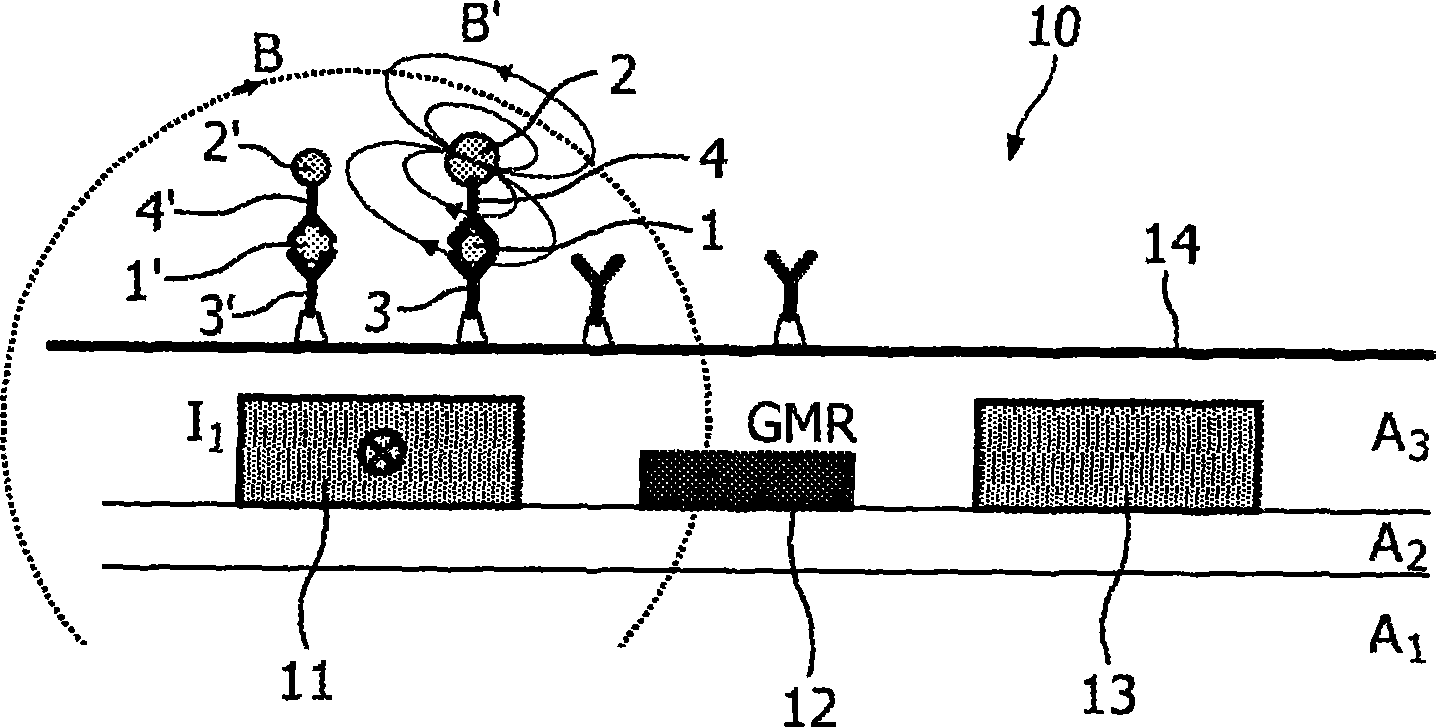
[0049] figure 1 A microelectronic magnetic sensor device 10 according to the invention is shown, which has particular application as a biosensor in the detection of magnetically interacting particles, such as superparamagnetic beads 2, 2' in a sample chamber. Magnetoresistive biochips or biosensors are promising biomolecular diagnostic tools in terms of sensitivity, specificity, integration, ease of use, and cost. Examples of such biochips are described in WO 2003 / 054566, WO 2003 / 054523, WO 2005 / 010542 A2, WO 2005 / 010543 A1 and WO 2005 / 038911 A1, which are hereby incorporated by reference.

[0050] Biosensors typically consist of figure 1 Composed of an array (eg 100) of sensor devices 10 of the type shown in , and thus can simultaneously measure a large number of different target molecules 1, 1' (eg, proteins, DNA, amino acids, drugs of abuse) in solution (eg, blood or saliva) )concentration. In one example of a possible binding scheme, the so-called "sandwich assay", this...


PUM


Abstract

The invention relates to a magnetic sensor device comprising excitation wires (11, 13) for generating a magnetic excitation field and a magnetic sensor element, particularly a GMR sensor (12), for sensing magnetic fields generated by labeling particles in reaction to the excitation field. The magnetic excitation fields are generated with non-sinusoidal forms, particularly as square-waves, such that their spectral range comprises a plurality of frequency components. Magnetic particles with different magnetic response characteristics can then be differentiated according to their reactions to the different frequency components of the excitation fields. The magnetic excitation field and the sensing current driving the GMR sensor (12) are preferably generated with the help of ring modulators (22, 24). Moreover, ring modulators (27, 29) may be used for the demodulation of the sensor signal.

Description

technical field [0001] The invention relates to a magnetic sensor device comprising at least one magnetic field generator, at least one associated magnetic sensor element and an associated power supply unit. Furthermore, the invention relates to the use of such a magnetic sensor device and a method for detecting magnetized particles with different magnetic properties. Background technique [0002] WO 2005 / 010543 A1 and WO 2005 / 010542 A2 disclose a microsensor device which can be used, for example, in a microfluidic biosensor for detecting molecules, such as biomolecules labeled with magnetic beads. The microsensor device is provided with a sensor array comprising wires for generating an alternating sinusoidal magnetic field and giant magnetoresistance (GMR) for detecting stray fields generated by magnetized, immobilized beads. The GMR's signal then indicates the number of beads near the sensor. [0003] A problem with measurements using a magnetic sensor device of the afor...

Claims


Application Information

Patent Timeline
IPC IPC(8): G01N15/06G01N33/543G01N35/00G01R33/09G01R33/12
CPCG01R33/12G01R33/093G01R33/1269G01N27/745B82Y25/00G01R33/09G01N33/54333G01N2446/00
Inventor J·A·H·M·卡尔曼A·H·J·伊明克H·杜里克A·J·M·范图伊吉勒E·坎塔托雷H·J·贝格维尔德
Owner KONINKLIJKE PHILIPS ELECTRONICS NV
Why Eureka
Try Eureka