
Battery apparatus, protection circuit, temperature monitoring method and temperature sensor laying method

A battery device and sensor technology, which is applied to emergency protection circuit devices, circuit devices, and secondary battery repair/maintenance, etc., can solve the problems of failure of protection, poor monitoring accuracy of temperature distribution in battery pack space, and insufficient warning conditions. To achieve the effect of reducing the risk of safety accidents

Active Publication Date: 2010-12-08
LENOVO (BEIJING) LTD
View PDF3 Cites 0 Cited by
  • Summary
  • Abstract
  • Description
  • Claims
  • Application Information

AI Technical Summary

Problems solved by technology

[0011] In the process of realizing the present invention, the inventors have found that there are at least the following problems in the prior art: (1) only real-time absolute temperature is monitored, and in the case of an internal short circuit of the cell, the protection function is completely invalid; (2) only absolute temperature is monitored. The temperature does not have an alarm function; (3) the absolute temperature is used as the early warning temperature judgment, and the early warning conditions are not sufficient; (4) the setting of the temperature monitoring point is relatively random, resulting in poor monitoring accuracy of the temperature distribution inside the battery pack

Method used


Image

  • Battery apparatus, protection circuit, temperature monitoring method and temperature sensor laying method
  • Battery apparatus, protection circuit, temperature monitoring method and temperature sensor laying method
  • Battery apparatus, protection circuit, temperature monitoring method and temperature sensor laying method

Examples


Embodiment 1

[0049] According to an embodiment of the present invention, a battery device is firstly provided.

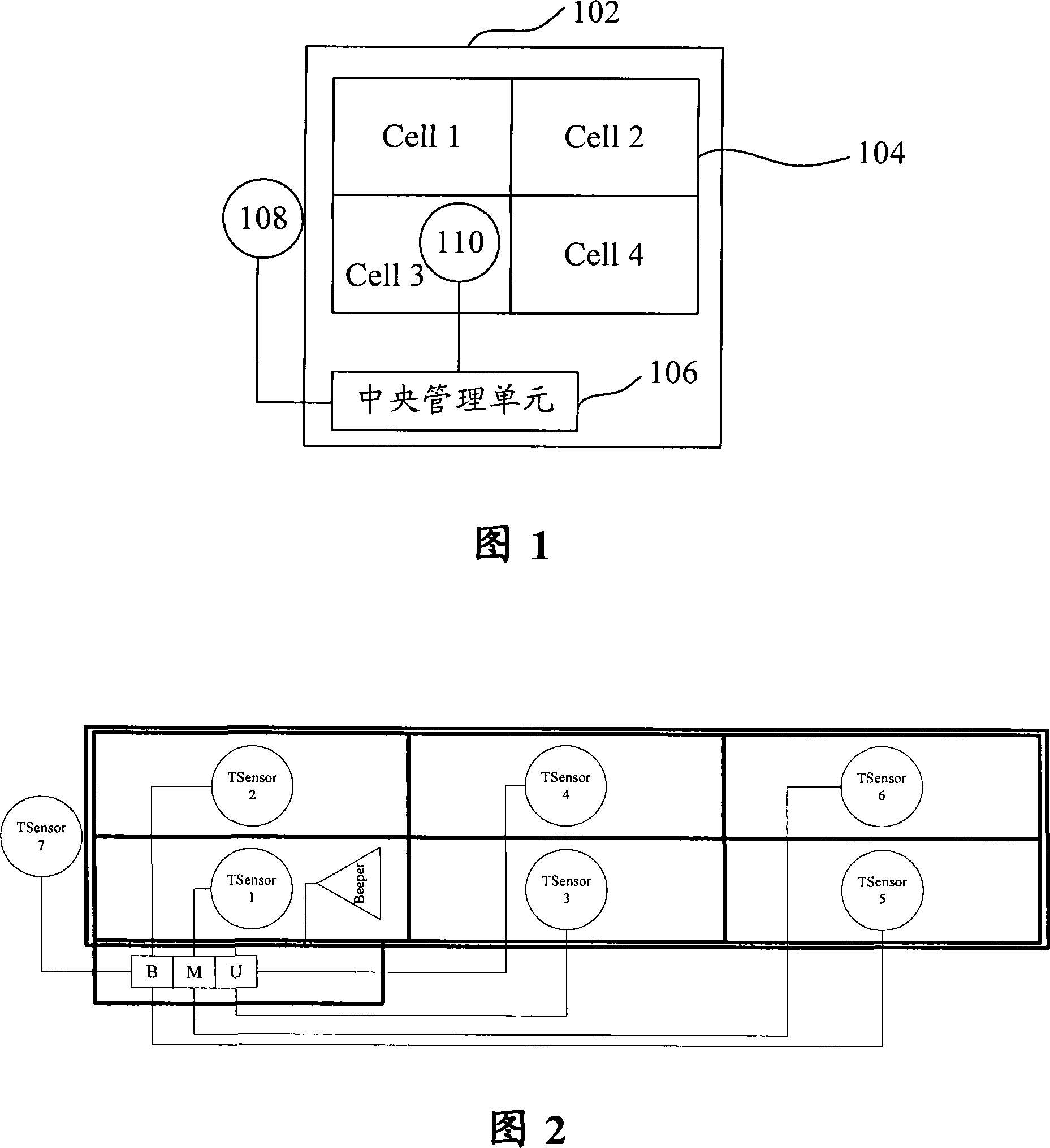
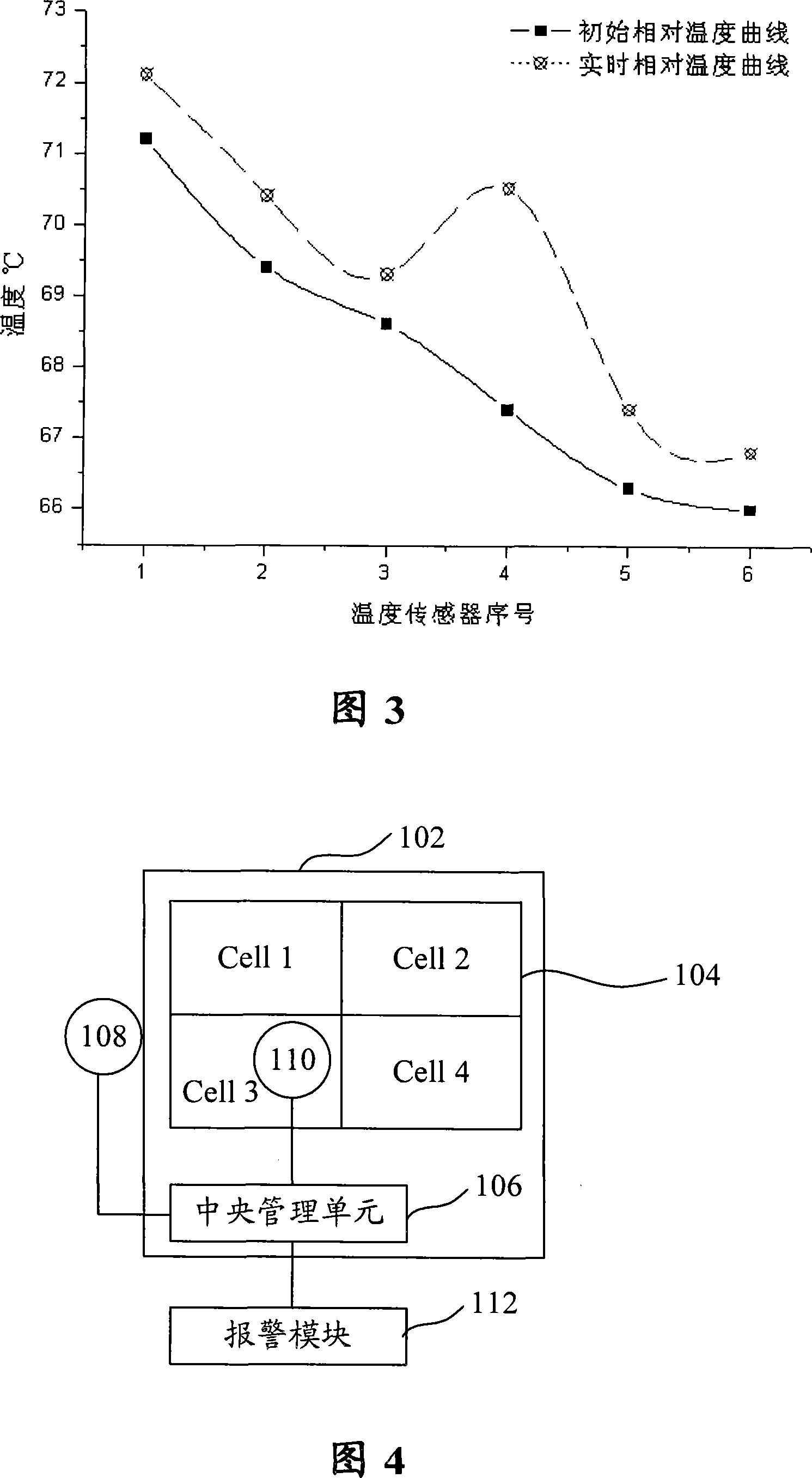
[0050] Such as figure 1 As shown, the battery device according to the embodiment of the present invention includes a casing 102, a cell unit 104, and a central management device 106, wherein the cell unit 104 and the central management device 106 are accommodated in the casing 102, and the cell unit consists of one or Consists of multiple batteries (Cell), figure 1 Four cells (Cell1-Cell4) are exemplarily shown in .

[0051] Such as figure 1 As shown, the battery device according to the embodiment of the present invention further includes: at least one external temperature sensor 108 ( figure 1 exemplarily shows one), connected to the housing 102; at least one internal temperature sensor 110, connected to the cell unit 104; in addition, both the external temperature sensor 108 and the internal temperature sensor 110 are connected to the central management device 106.

[0052...

Embodiment 2

[0072] According to an embodiment of the present invention, a protection circuit for a battery device is provided.

[0073] Such as Figure 9 As shown, the protection circuit includes: at least one external temperature sensor 902 (one is shown as an example in the figure), connected to the casing of the battery device; at least one internal temperature sensor 904 (one is shown as an example in the figure) ), connected to the cell unit of the battery device; the central management device 906, connected with the external temperature sensor 902 and the internal temperature sensor 904, obtains the sensing temperature of the external temperature sensor 902 and the internal temperature sensor 904, and according to the obtained sensing temperature The relative temperature is obtained by a predetermined algorithm (for example, subtraction), and then the initial relative temperature curve or surface data and the process relative temperature curve or surface data are recorded according ...

Embodiment 3

[0077] According to an embodiment of the present invention, a method for monitoring the temperature of a battery device is provided. The monitoring method can preferably be implemented using the battery device of Embodiment 1 and the protection circuit of Embodiment 2, or can also be implemented using other suitable devices. The present invention is not particularly limited thereto.

[0078] Such as Figure 10 As shown, the method for monitoring the temperature of a battery device according to an embodiment of the present invention includes the following processing:

[0079] Step S1002, sensing the initial external temperature or initial internal temperature of each monitoring point of the battery device under different working conditions, obtaining the initial relative temperature through a predetermined algorithm according to the initial internal temperature and the initial external temperature, and forming different working conditions according to the initial relative tempe...


PUM


Abstract

The invention discloses a battery device, a battery device protection circuit and a method of monitoring the temperature of the battery device. The battery device comprises a shell, an electric core unit and a central management unit; wherein, the electric core unit and the central management unit are arranged in the shell; and the electrical core unit comprises a or a plurality of electrical core(s). The battery device of the embodiment of the invention further comprises at least one outer temperature sensor which is connected with the shell and at least one inner temperature sensor which isconnected with the electrical core unit(s); and the outer temperature sensor and the inner temperature sensor are both connected with the central management unit (BMU). Preferentially, the battery device comprises a warning module. The invention can effectively monitor the electrical core unit and even the decline performance of each electrical core. Due to the warning function, the invention canalarm before the safety-related incident of the battery occurs, thereby effectively reducing the risk of safety incidents.

Description

technical field [0001] The present invention relates to a battery (especially a lithium ion battery) and monitoring of battery temperature, in particular to a battery device, a protection circuit of the battery device, a temperature monitoring method of the battery device, and an arrangement method of a temperature sensor of the battery device. Background technique [0002] Currently, the batteries used in mobile terminals such as notebook computers on the market are generally battery packs, and the inside of the battery pack generally has three to nine battery cells. The protection circuit part inside the battery pack is used to monitor the overcurrent, overcharge, and overdischarge of the cells connected in series and in parallel, and to monitor the temperature of certain points inside the battery pack. The following uses the battery of a notebook computer as an example for description. [0003] However, even with the monitoring and protection of the protection circuit, t...

Claims


Application Information

Patent Timeline
Patent Type & Authority Patents(China)
IPC IPC(8): H01M10/48H01M10/44H02H7/18H02H5/04
CPCY02E60/12Y02E60/10
Inventor 于海峰
Owner LENOVO (BEIJING) LTD
Learn More