

Surgical stapling apparatus with control features operable with one hand
A technique for surgical stapling instruments and handles, applied in surgical equipment, surgical fixation pins, surgery, etc., can solve problems such as lack of available space
- Summary
- Abstract
- Description
- Claims
- Application Information
AI Technical Summary
Problems solved by technology
Method used
Image

Examples
Embodiment Construction
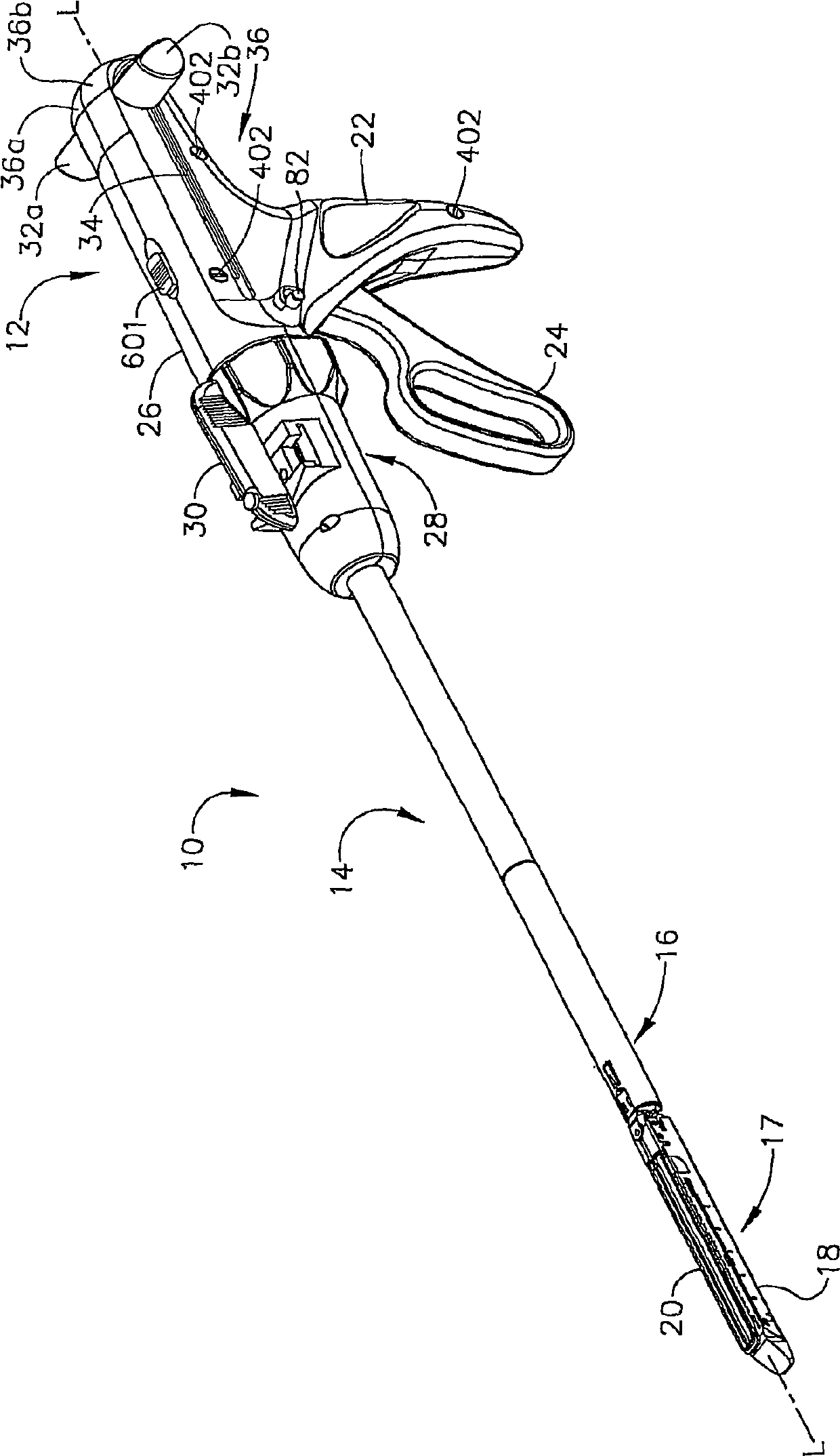
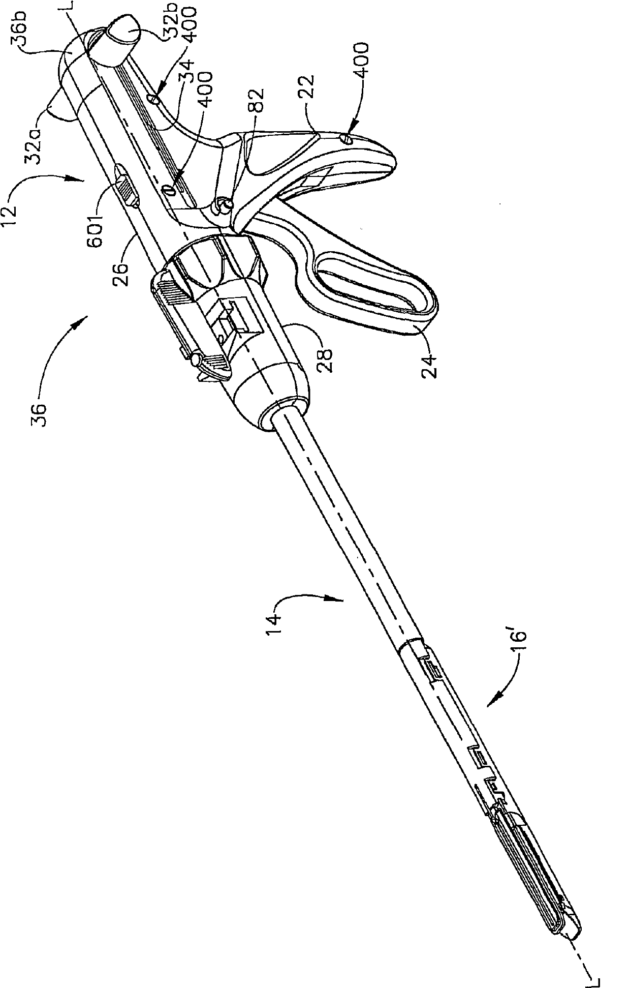
[0202] Referring to the drawings, wherein like reference numerals denote like elements throughout, figure 1 Illustrated is a reusable surgical instrument, more specifically a surgical stapling instrument 10 capable of realizing the unique advantages of various embodiments of the present invention in a typical approach. Surgical stapling instrument 10 may include a handle assembly 12 and an elongated body 14 . figure 1 Surgical stapling instrument 10 is shown with articulable disposable loading unit 16 attached thereto. figure 2 Surgical stapling instrument 10 is shown with a non-articulable disposable loading unit 16' attached thereto. The disposable loading unit 16, 16' can include a tool assembly 17 that includes a cartridge assembly 18 that receives a plurality of surgical staples therein. Tool assembly 17 may further include staple forming anvil 20 . The disposable loading unit 16, 16' can perform surgical procedures such as cutting tissue and applying staple...
PUM
 Abstract
Description
Claims
Application Information