
Tractor and printer with the tractor

A technology of tractor and main body, applied in the field of printers

Inactive Publication Date: 2012-02-22
CITIZEN SYST JAPAN
View PDF4 Cites 0 Cited by
  • Summary
  • Abstract
  • Description
  • Claims
  • Application Information

AI Technical Summary

Problems solved by technology

[0009]The Although the tractor shown in Figure 5 can allow excessive rotation of the cover 5 and can prevent damage or damage to the support portion (bearing portion) 14 on the main body 4 side, it must be made with sufficient strength to consider the strength. The upper part of the thick-walled bearing groove 16 deflects, and considerable pressure needs to be applied, so that the stop 17 is worn early and it becomes difficult to stabilize the cover 5 in the open position.
In addition, when the shaft 15 on the side of the cover 5 falls out of the bearing groove 16 on the side of the main body 4, in terms of the structure of the tractor 2, it is troublesome for an unfamiliar user to restore it.

Method used


Image

  • Tractor and printer with the tractor
  • Tractor and printer with the tractor
  • Tractor and printer with the tractor

Examples


Embodiment Construction

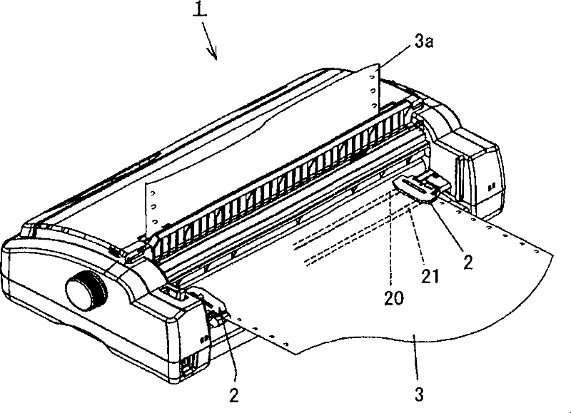
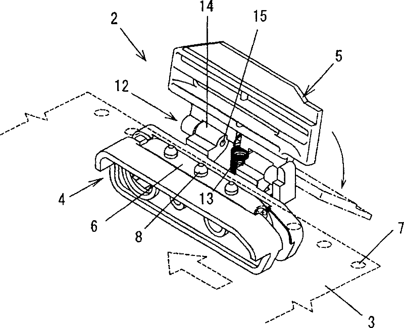
[0034] The retractor 2 has a main body 4 , a cover 5 and a tension coil spring 13 . The main body 4 is made of hard synthetic resin, such as Figure 6 As shown, there is a supply figure 1The drive shaft penetration hole 18 through which the drive shaft 20 is inserted is formed behind (on the upstream side in the paper conveyance direction A) for a feeder. figure 1 The guide shaft penetration hole 19 through which the guide shaft 21 is shown penetrates.

[0035] The drive shaft 20 and the guide shaft 21 are erected on the side parallel to the left-right direction (direction perpendicular to the conveyance direction of the continuous paper 3). figure 1 In the printer 1, these shafts 20, 21 pass through the through holes 18, 19 of the tractor 2, whereby the tractor 2 is supported by these shafts 20, 21.

[0036] The cross section of the drive shaft 20 penetrating the drive shaft through hole 18 is substantially rectangular, and the drive shaft 20 penetrates a drive sprocket...


PUM


Abstract

The left and right tractors arranged on the printer and conveying the continuous paper to the printing section are respectively composed of a main body (4) and a cover (5). The shaft (15b) provided on the main body (4) side passes through the long hole (26) formed on the cover (5) side, whereby the cover (5) can be opened and closed relative to the main body (4). A coil spring (13) is erected between the main body (4) and the cover (5). During further movement of the cover (5) from the closed position beyond the open position to the over-rotated position, the shaft (15b) in the elongated hole (26) moves from one end to the other.

Description

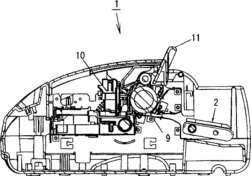
technical field [0001] The present invention relates to an improvement of a tractor used in a printer for printing on continuous recording paper and a printer using the improved tractor. Background technique [0002] like figure 1 and figure 2 As shown, the printer 1 using continuous paper (roll paper, fanfold paper) usually uses the left and right tractors 2 to send the continuous paper 3 (paper feed) into the printing section, so that the continuous paper 3 (paper discharge) after typing 3a) is discharged from the printer 1 via discharge rollers. In addition, in figure 2 In the drawing, reference numeral 9 denotes a platen, reference numeral 10 denotes a printing head, and reference numeral 11 denotes a guide portion for discharging the continuous paper 3 . [0003] like image 3 and Figure 4 as shown, figure 1 The retractor 2 shown consists of a main body 4 and a cover 5 which is switchable relative to the main body. image 3 The tractor 2 is shown with the ...

Claims


Application Information

Patent Timeline
Patent Type & Authority Patents(China)
IPC IPC(8): B41J11/30B41J15/04B65H20/20
Inventor 岩田安夫
Owner CITIZEN SYST JAPAN
Learn More