
Pressure vessel arrangement

A pressure vessel and differential pressure technology, applied in the field of pressure vessel devices, can solve the problem of unutilized installation space and other problems

Active Publication Date: 2022-03-01
BAYERISCHE MOTOREN WERKE AG
View PDF5 Cites 0 Cited by
  • Summary
  • Abstract
  • Description
  • Claims
  • Application Information

AI Technical Summary

Problems solved by technology

[0003] It has been shown that the corresponding installation space is not well utilized by conventional large-volume spherical-cylindrical tanks
Whereas the design of chained tanks or tube storage, such as here, promises a better solution, but poses structure-specific problems

Method used


Image

  • Pressure vessel arrangement
  • Pressure vessel arrangement
  • Pressure vessel arrangement

Examples


Embodiment Construction

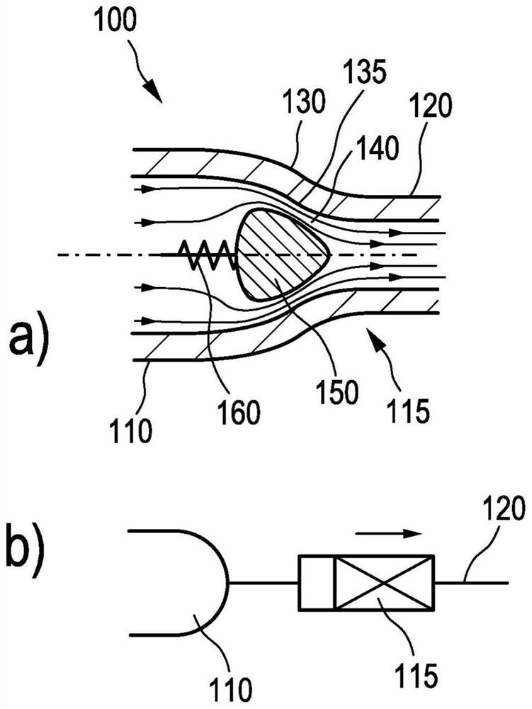
[0040] figure 1 a shows a section of the pressure vessel arrangement 100 , more precisely the transition between a pressure vessel 110 and the connecting line 120 connected thereto. A narrowing 130 is formed between the pressure vessel 110 and the connecting line 120 . A safety valve 115 is formed in the taper, which will be described in more detail below.

[0041] The safety valve 115 has a valve body 150 . The valve body is fixed on a pretensioning device in the form of a spring 160 which allows the valve body 150 to figure 1 In the illustration of a, it is moved in the horizontal direction and is here pretensioned to the left away from the narrowing 130 . In this case, valve body 150 is surrounded by a fluid flow, which is indicated by arrows. The fluid flow is thus in figure 1 Flow from left to right in the illustration of a.

[0042] Between the valve body 150 and the narrowing 130 a compression 140 of the flow lines takes place, which leads to a negative pressure w...


PUM


Abstract

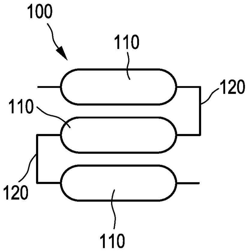
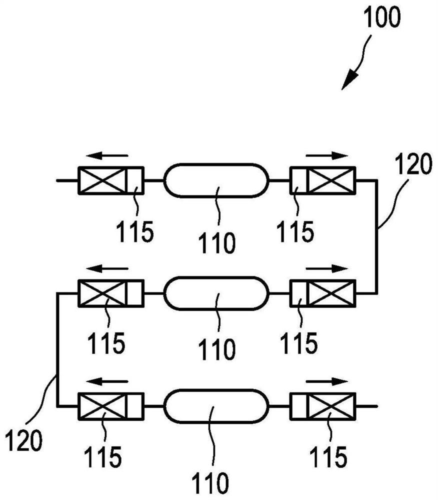
The technology disclosed herein relates to a pressure vessel arrangement 100 according to the invention comprising a plurality of pressure vessels 110, a number of relief valves 115 arranged between the pressure vessels 110 so as to close from a predetermined maximum flow rate and / or from a predetermined maximum pressure differential, and a number of connecting lines 120. Therefore, the influence of leakage can be reduced.

Description

technical field [0001] The technology disclosed herein relates to a pressure vessel arrangement that may be used, for example, to store fuel under pressure in a motor vehicle. Background technique [0002] For future motor vehicles, increased use of alternative fuels such as pressurized hydrogen is planned. The same applies to other gases stored at high pressure, liquefied and / or cryogenic. In order to increase the cruising range of such motor vehicles, it has been found to be advantageous if the pressure vessel used as a storage tank fits as ideally as possible into the existing installation space, i.e. has a small dead space, in order to make full use of the existing installation Space to store gaseous fuel. For example, the corresponding installation space can be cuboid-shaped and / or have a limited height. [0003] It has been shown that the corresponding installation space is not well utilized by conventional large-volume spherical cylindrical storage tanks. Whereas ...

Claims


Application Information

Patent Timeline
Patent Type & Authority Applications(China)
IPC IPC(8): F17C13/04
CPCF17C13/04F17C2201/0138F17C2205/013F17C2205/0138F17C2205/0332F17C2205/0335F17C2221/012F17C2270/0178F17C2203/0619F17C2270/0168F17C2201/0128F17C2201/058F17C2203/0663F17C2205/0142F17C2223/0123F17C2260/036Y02E60/32F17C2203/0604F17C2205/0134
Inventor H-U·斯塔尔
Owner BAYERISCHE MOTOREN WERKE AG
Learn More