Eureka AIR delivers breakthrough ideas for toughest innovation challenges, trusted by R&D personnel around the world.

Dehumidifier

A dehumidifier and humidity technology, applied in mechanical equipment, heating methods, lighting and heating equipment, etc., can solve the problems that it is difficult to fully inhibit mold and local humidity does not decrease, and achieve the effect of inhibiting the occurrence of mold

Active Publication Date: 2009-08-19
MITSUBISHI ELECTRIC CORP +1
View PDF3 Cites 11 Cited by
  • Summary
  • Abstract
  • Description
  • Claims
  • Application Information

AI Technical Summary

Problems solved by technology

[0007] In the past dehumidifiers, the low humidity retention time was judged based on the temperature and relative humidity of the indoor air. However, in environments where mold is prone to grow, such as bathrooms, and places where water droplets are easy to accumulate, such as bathroom floors, water droplets accumulate for a long time, even if the air The relative humidity in the environment decreases, and there are also parts where the local humidity does not decrease, so it is difficult to fully inhibit the production of mold

Method used


Image

  • Dehumidifier
  • Dehumidifier
  • Dehumidifier

Examples


Embodiment Construction

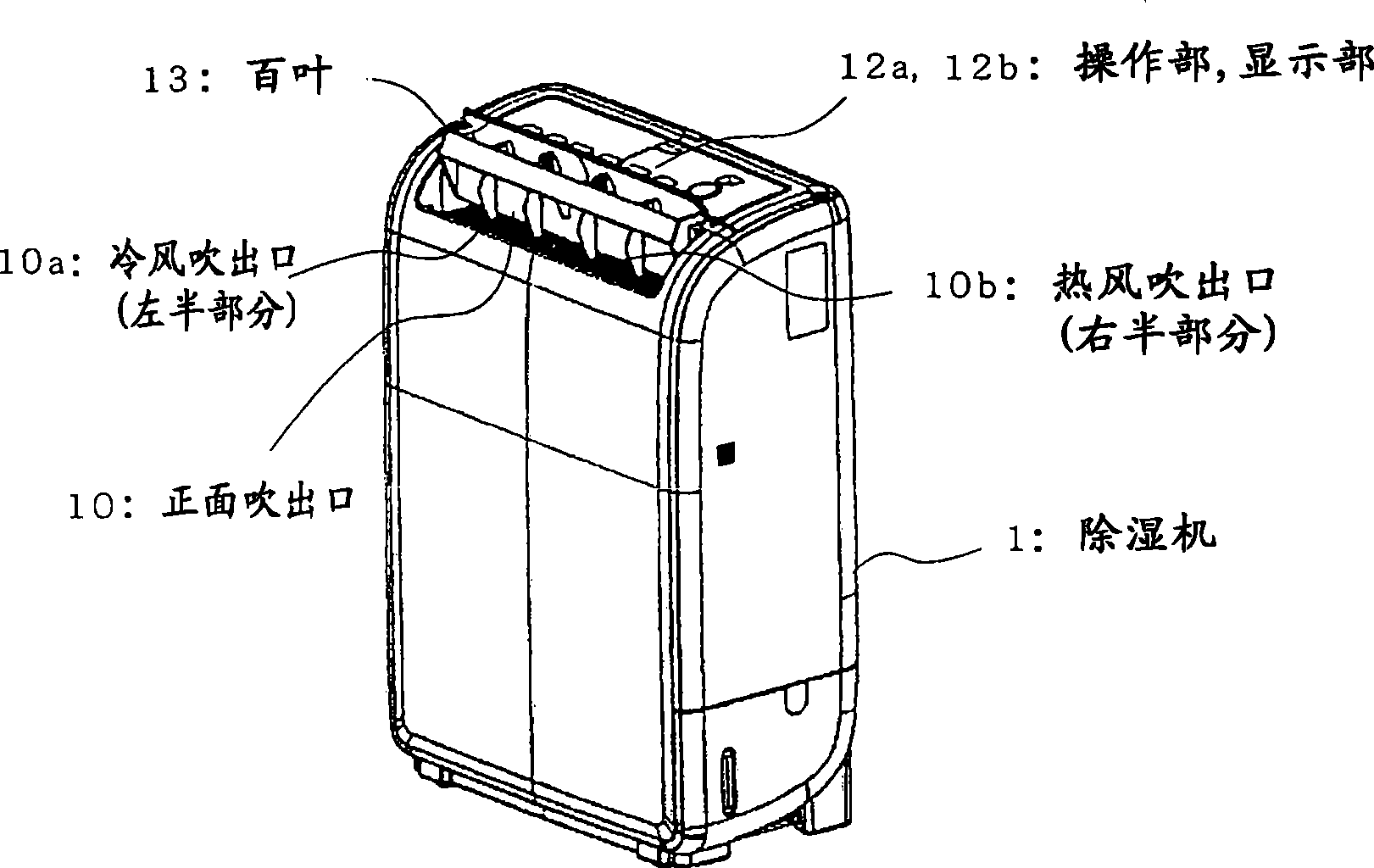
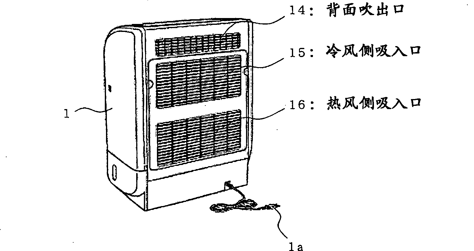
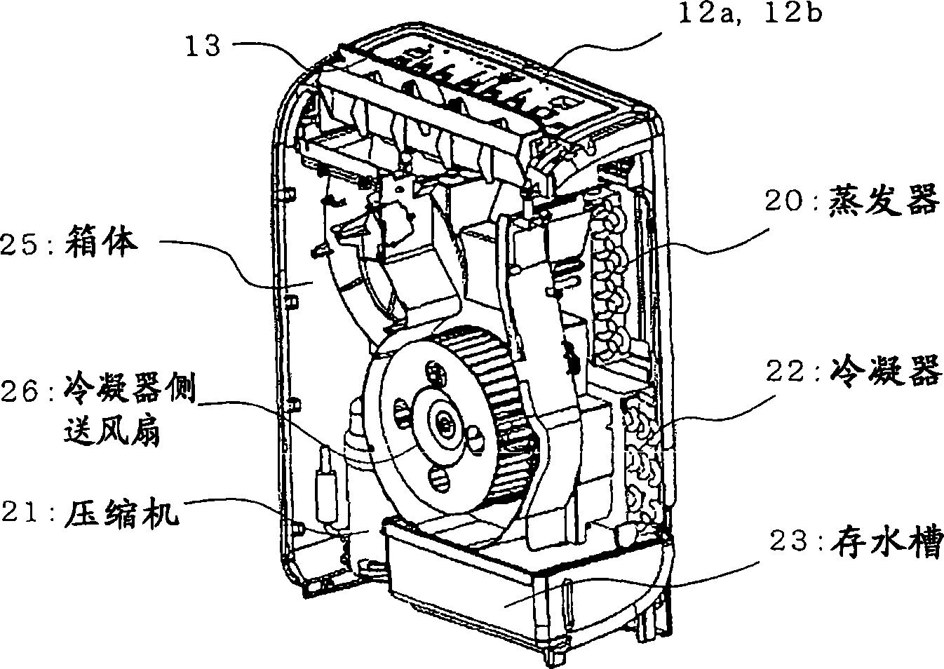
[0029] figure 1 An appearance view viewed from the front side of a dehumidifier with a cooling function (hereinafter referred to as a dehumidifier) ​​according to an embodiment of the present invention. figure 2 It is the exterior view seen from the back side. image 3 It is a structural diagram showing the internal structure of the dehumidifier with the front and side exterior parts removed.

[0030] Dehumidifier 1, such as figure 1 Shown, in the front side (closer side) of its top, have formed front blowing outlet 10, and its left half is cold wind blowing outlet 10a, and right half is hot blast blowing outlet 10b. In the front blower 10, the operation part 12a and the display part 12b are respectively provided in the back side. In addition, the front air outlet 10 is provided with a louver 13 that can automatically open and close to cover the front air outlet 10, and the louver 13 is rotated to adjust the opening area of ​​the front air outlet 10, so that the blowing ...


PUM


Abstract

The invention provides a dehumidifier that inhibits growth of mould fungus, being provided with a cold air side absorption hole (15), a hot air side absorption hole (16) and a front absorption hole (10), a shutter (13) that brings automatic change of a blowing direction of treated air, an apparatus (20, 22) that humidifies or heats air absorbed so as to reduce relative humidity, a room temperature detection mechanism (31) that detects the room temperature, a humidity detection mechanism (32) that detects humidity, a control portion (30) that operates or stops automatically according to the room temperature and the humidity, to thereby change the blowing range of treated air according to the room temperature or humidity.

Description

technical field [0001] The present invention relates to a dehumidifier equipped with a dehumidifying or drying device, and particularly relates to the operation control of the outlet, the shape of the outlet and the control of the dehumidification operation. Background technique [0002] Conventional dehumidifiers determine the low humidity retention time based on the temperature and relative humidity of the indoor air, perform dehumidification operation, and adjust the indoor humidity (for example, see Patent Document 1). In addition, it is pointed out in the prior art that when the relative humidity of the environment is adjusted to 40-60%, it has the effect of inhibiting the growth of mold (for example, see Patent Document 2 and Patent Document 3). [0003] Patent Document 1: Japanese Patent Laid-Open No. 2001-248880 (Abstract, Figure 6 ) [0004] Patent Document 2: Japanese Patent Application Laid-Open No. 7-275329 (page 3) [0005] Patent Document 3: Japanese Patent ...

Claims


Application Information

Patent Timeline
IPC IPC(8): F24F1/02F24F11/00B01D53/26F24F11/02F24F11/76
Inventor 久下洋介柴田英雄
Owner MITSUBISHI ELECTRIC CORP
Why Eureka
Eureka Blog
Learn More