
Furniture hinge

A technology for hinges and furniture, which is applied to hinges with pins, door/window fittings, wing parts, etc., and can solve the problem of small buffering stroke and other problems

Active Publication Date: 2013-03-06
HETTICH ONI
View PDF2 Cites 0 Cited by
  • Summary
  • Abstract
  • Description
  • Claims
  • Application Information

AI Technical Summary

Problems solved by technology

But this rotary buffer only has a limited damping force and the damping stroke is quite small

Method used


Image

  • Furniture hinge

Examples


Embodiment Construction

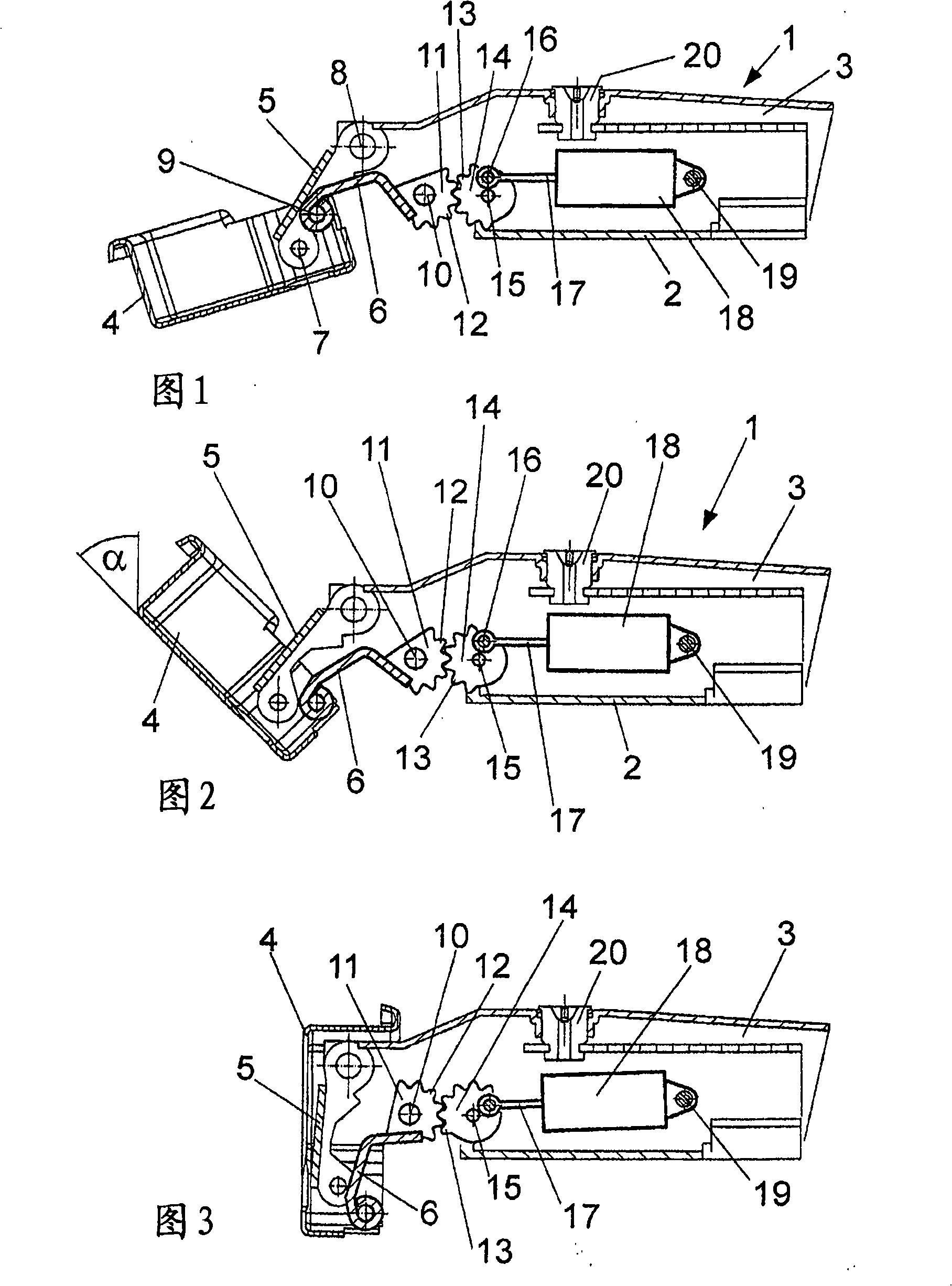
[0014] Furniture hinges made of metal or plastic comprise a mounting plate 2 which can be fastened to a furniture. A side part 3 is mounted adjustably on the mounting plate 2 , wherein a pot-shaped hinge part 4 is pivotally mounted on the side part 3 via a support rod 5 and a guide rod 6 . The hinge part can be fixed on the groove of a furniture door. The support rod 5 is connected via a shaft 7 to the hinge part 4 and via a shaft 8 to the side part 3 . The guide rod 6 is connected to the hinge part 4 via the shaft 9 and to the side part 3 via the shaft 10 .

[0015] A projection 11 with a toothing 12 is integrally formed on the guide rod 6 . The toothing 12 meshes with a toothing 13 on a wheel 14 designed as a rotor, which is mounted rotatably about an axis 15 on the side part 3 . The toothing 13 is partially provided on the wheel 14 since only a limited portion of the wheel 14 meshes with the toothing 12 . A pin 16 is provided on the wheel 14 at a distance from the shaft...


PUM


Abstract

A furniture hinge comprises an installation plate (2) on which a side part (3) is arranged, and a hinge part (4) which is held pivotably on the side part (3) via a supporting lever (5) and a guide lever (6), wherein, to damp the movement of the hinge part (4) relative to the side part (3), a linear damper is provided, with a housing (18) and a piston rod (17) which, for damping purposes, are coupled to a rotary part (14) which is driven rotatably about an axis (15) by the supporting lever (5) or the guide lever (6), which permits a compact construction with the possibility of compensating for tolerances.

Description

technical field [0001] The invention relates to a furniture hinge, comprising a mounting plate, on which a side part is arranged; and a hinge part, which is rotatably supported on the side part by means of a support rod and a guide rod. Background technique [0002] EP1555372 discloses a furniture hinge in which a hinge part is pivotally mounted on the side part via a support rod and a guide rod. To dampen the movement of the hinge parts, a linear damper is provided on the side parts, which is coupled via a link to a projection on the guide rod. In this case, the coupling is designed rigidly, so that only limited tolerance compensations are possible. In addition, the assembly of each component is relatively troublesome. [0003] DE10159140 discloses a furniture hinge in which, in order to dampen the movement of the hinge parts, a swivel damper can also be provided in the side parts. The swivel damper operates via a pinion and a toothing profile, so that a certain damping ...

Claims


Application Information

Patent Timeline
Patent Type & Authority Patents(China)
IPC IPC(8): E05F5/00E05F5/02E05D3/06
CPCE05D3/142E05Y2900/20E05Y2201/71E05Y2201/254E05Y2600/41E05F5/02E05Y2201/264E05Y2201/21E05F5/006E05Y2600/45E05Y2201/712
Inventor W·贝克曼K-M·施图克O·舍尔R·米特尔蒂斯M·舒伯特J·克勒夫曼
Owner HETTICH ONI
Learn More