
Unloading device for containers and method for operating them

a technology for unloading devices and containers, applied in safety gear, load-engaging elements, trolley cranes, etc., can solve problems such as inability to meet simple conditions, and achieve the effect of simple mechanical coupling

Inactive Publication Date: 2014-02-06
GE ENERGY POWER CONVERSION
View PDF7 Cites 1 Cited by
  • Summary
  • Abstract
  • Description
  • Claims
  • Application Information

AI Technical Summary

Benefits of technology

The present invention provides a loading device for containers that has at least two load handling devices and uses a simple mechanical coupling for easy connection. The device also includes a distance sensor to measure the distance of the load handling devices from the travel carriage and adjust them to be on the same level. This eliminates any difference in the load handling devices in terms of their height and makes them easy to connect. The technical effect of this invention is to provide a reliable and efficient loading device for containers.

Problems solved by technology

This condition cannot be met in a simple manner, since the supporting cables undergo an expansion over time owing to the loads that are transported, which could be different at the two load handling devices.

Method used


Image

  • Unloading device for containers and method for operating them
  • Unloading device for containers and method for operating them
  • Unloading device for containers and method for operating them

Examples


Embodiment Construction

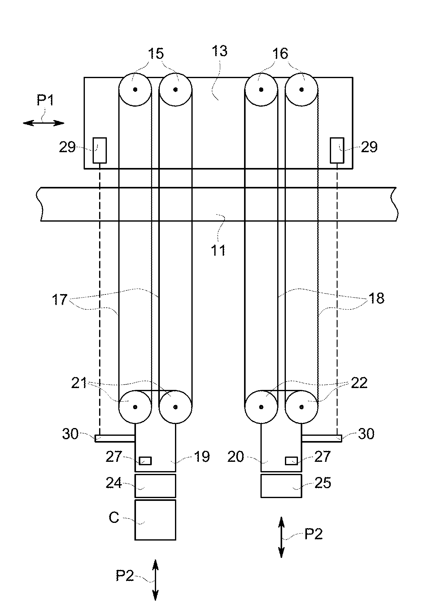
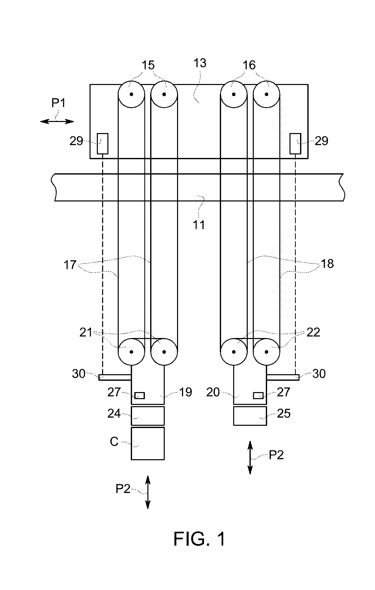
[0019]Harbors and loading docks often employ a loading device with which containers are loaded onto and off of ships, trucks, trains or other transport vehicles. Such a loading device for containers often takes on the form of a gantry crane, which can be moved along a quay and hence is essentially parallel to a ship that is moored there. The loading device has a loading bridge with several rails, which are arranged at a height such that they are essentially located above a loading area that is present on the ship. The rails can be moved to a position in which they are approximately transverse with respect to the quay and hence also approximately perpendicular to a ship that is moored there. In this position the rails project over and above the ship. At least one travel carriage, which can be moved in the direction of the rails, is arranged on these rails. With the help of this loading device containers can be loaded onto or off the ship.

[0020]FIG. 1 shows a rail 11 of such a loading...


PUM


Abstract

A loading device for containers, which is provided with a travel carriage, which can move on a rail. Furthermore, there are two load handling devices which are assigned to the travel carriage, and which are kept fixed to the travel carriage with the help of the supporting cables. Each of the load handling devices can be raised or lowered, and the two load handling devices can be coupled mechanically with each other. A distance sensor is assigned to each of the load handling devices, with which the distance of the load handling devices from the travel carriage can be determined.

Description

CROSS-REFERENCE TO RELATED APPLICATIONS[0001]This application claims foreign priority under 35 U.S.C. §119 to co-pending German Patent Application No. 102012213604.5, filed Aug. 1, 2012, which is hereby incorporated by reference in its entirety.BACKGROUND OF THE INVENTION[0002]Embodiments of the present invention relate to a loading device for containers as well as a method for operating them.[0003]A loading device for containers is known, for example, from the WO 2010 / 007514 A2 (“Fantuzzi”). FIG. 1 of Fantuzzi, for instance, shows two load bearing load handling devices 2, 3, to each of which a spreader 6, 11 is attached in a detachable manner, against which, in turn, containers C1, C2 can be held in a detachable manner. At each of the load handling devices 2, 3, pulleys 7, 13 are arranged, over which the supporting cable or ropes 8, 14, from which the load handling devices 2, 3 are suspended, are guided.[0004]Normally, in such loading devices, a travel carriage is assigned to the t...

Claims


Application Information

Patent Timeline
Patent Type & Authority Applications(United States)
IPC IPC(8): B66C13/18B66C19/00
CPCB66C19/002B66C13/18B66C1/104B66C13/46B66C1/10
Inventor STEINHAUS, LUTZTESSMER, TOBIAS
Owner GE ENERGY POWER CONVERSION
Learn More