Check patentability & draft patents in minutes with Patsnap Eureka AI!

Image displacement detection method

An image and displacement technology, applied in the direction of instrument, electrical digital data processing, data processing input/output process, etc., can solve the problems of unable to find sub-blocks, unable to find image displacement vector, lack of image features 14b, etc.

Inactive Publication Date: 2009-09-02
ELAN MICROELECTRONICS CORPORATION
View PDF0 Cites 3 Cited by
  • Summary
  • Abstract
  • Description
  • Claims
  • Application Information

AI Technical Summary

Problems solved by technology

[0012] exist Figure 2B , the image 12c lacks the image feature 14b in the center of the image 12b, so the conventional image displacement detection method will not be able to find the best matching sub-block in the image 12c, nor can it find the image displacement vector

Method used


Image

  • Image displacement detection method
  • Image displacement detection method
  • Image displacement detection method

Examples


Embodiment Construction

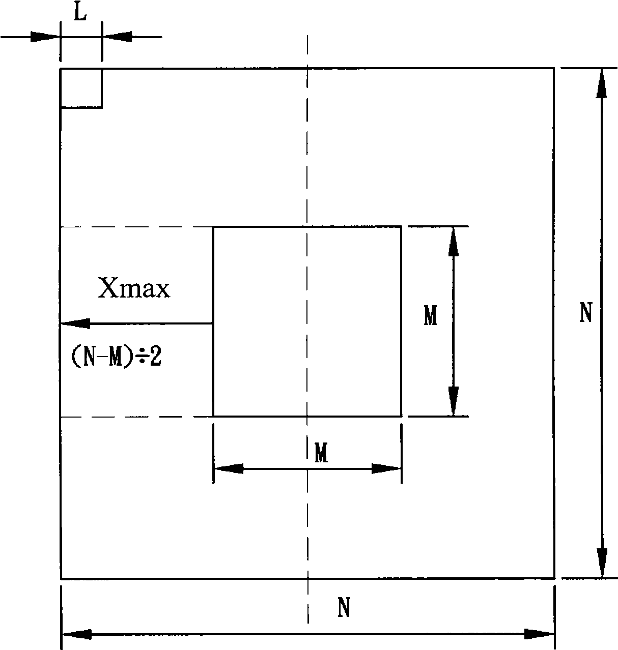
[0026] Please refer to Figure 3A and Figure 3B program A, also in Figure 2A-2B In the state shown, when the image displacement detection is performed for the first time, since there is no previous image displacement vector at the beginning, the center of the first time image 12a (that is, the first continuous image 12a) is taken A square block is used as an image comparison reference block, and the size of the image comparison reference block may be M*M. Then, starting from the upper left corner of the second time image 12b (that is, the second continuous image 12b), an M*M sub-block of the same size is taken out to compare with the image comparison reference block to see if it matches ( or the same), if it does not match (or not the same), then move one pixel to the right and take out another M*M sub-block, and then compare it with the image comparison reference block to see if it matches (or is the same) In this way, from left to right and from top to bottom in the ent...


PUM


Abstract

The image displacement detection method in the invention uses the center of a first time image as a starting point and previous image displacement vector or the reverse direction displacement position of the regulated previous image displacement vector as an image comparing benchmark block, and then compares a second time image, thus obtaining the image displacement vector between the first time image and the second time image. In this way, the method can approximately double the maximum tracking velocity of sensors relatively.

Description

technical field [0001] The present invention relates to an image displacement detection method, especially to an image displacement detection method applied to a sensor (such as a sensor of an optical mouse), which can relatively double the maximum tracking speed (Max Tracking Speed) of the sensor. Background technique [0002] The traditional typical block matching algorithm (Block Matching Algorithm) is fixed at the first time image (1 st Frame) selects a block smaller than the first time image as the reference block (Reference Block), and then uses this reference block to compare the second time image (2 nd Frame) for comparison and search. The comparison method is to divide the second time image into blocks of the same size as the reference block, which are called Sample Blocks, and then pass the mean absolute value error (Mean Absolute Difference (MAD for short) or Mean Square Error (MSE for short) block calculation, calculate the similarity between each pixel, and f...

Claims


Application Information

Patent Timeline
Patent Type & Authority Applications(China)
IPC IPC(8): G06F3/038G06F3/0354
Inventor 张进邦戴文村
Owner ELAN MICROELECTRONICS CORPORATION
Features
  • R&D
  • Intellectual Property
  • Life Sciences
  • Materials
  • Tech Scout
  • Unparalleled Data Quality
  • Higher Quality Content
  • 60% Fewer Hallucinations
Learn More