Nozzle for floor vacuum cleaner

A technology for vacuum cleaners and straws, applied in the direction of vacuum cleaners, nozzles, applications, etc., can solve problems such as loss of flexibility

Active Publication Date: 2013-04-03
威赛有限公司
View PDF2 Cites 3 Cited by
  • Summary
  • Abstract
  • Description
  • Claims
  • Application Information

AI Technical Summary

Problems solved by technology

But as a result, the suction head loses its flexibility to adapt to the floor surface
Also, the operation of the nozzle takes time to get used to and is not self-explanatory

Method used


Image

  • Nozzle for floor vacuum cleaner
  • Nozzle for floor vacuum cleaner
  • Nozzle for floor vacuum cleaner

Examples


Embodiment Construction

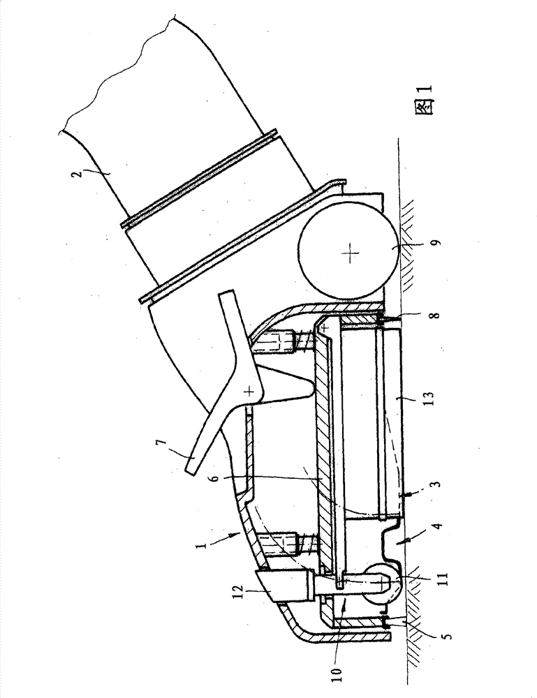
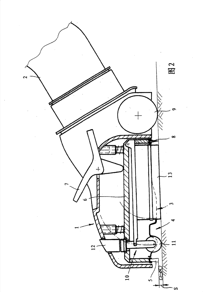
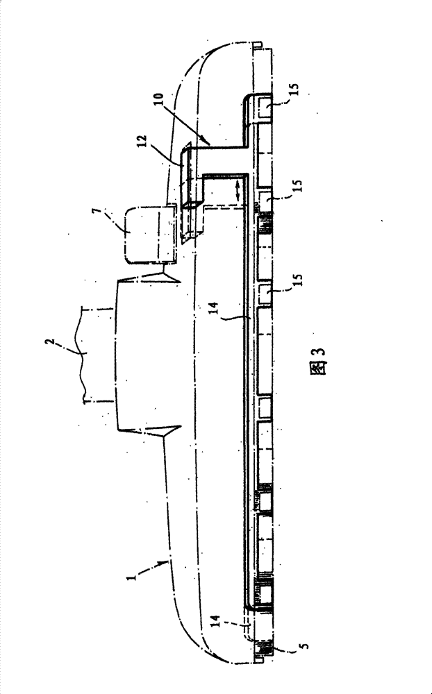
[0023] The nozzle shown in the picture can be attached to the vacuum cleaner via the suction tube and suction hose and is optimal for vacuuming on fabric surfaces and smooth floors. The basic structure of this suction nozzle consists of a suction head 1, a suction tube adapter 2, a sliding base 3, and a telescoping support and sealing element, wherein said suction tube adapter 2 is attached to the suction head in a movable manner about an axis of rotation Or a suction channel, which is rotatably connected to the suction head; the sliding base 3 has at least one lower side suction groove 4 defined by the edge of the suction port; the telescopic support and sealing The element for vacuuming smooth floors on the underside of the suction head comprises a front strip 5 which is breathable and / or has openings and is arranged upstream of the suction slot 4 in the suction direction. The front strip 5 is fixed to a vertically adjustable or rotatably arranged support 6 in the suction he...


PUM


Abstract

The suction nozzle has a suction head (1) and a suction tube connecting piece (2), which is attached around an axis of rotation moving to the vacuum generator with a vacuum generator connected suction channel. A separately adjustable additional device (10) is provided for sucking dirt, with which a base stand (s) of more than 2 millimeter is adjusted between the floor spaces that have to be cleaned. A flow cross section of opening is changed in a front strip (5).

Description

technical field [0001] The invention relates to a nozzle for a vacuum cleaner, the nozzle having: [0002] suction head; [0003] a suction tube connector movably attached to a suction head or a suction channel rotatably connected to the suction head about an axis of rotation; [0004] a sliding base having at least one underside suction slot defined by the edge of the mouthpiece; and [0005] Telescoping support and sealing element for vacuuming smooth floors on the underside, comprising a front strip which is breathable and / or has openings and arranged in the suction direction upstream of the suction slot, [0006] Therein, the front strip is fixed to a vertically adjustable or rotatably arranged support in the suction head, which support can be actuated by a switching element operable on the suction head. The front strip can be formed, for example, from a bristle strip with a profiled lower edge. Background technique [0007] A suction nozzle having the above-mention...

Claims


Application Information

Patent Timeline
Patent Type & Authority Patents(China)
IPC IPC(8): A47L9/06
CPCA47L9/066A47L9/0633A47L9/0653A47L9/02A47L9/06
Inventor D·卡芬伯格H·迪尔格T·林德K-D·里尔
Owner 威赛有限公司
Why Eureka
Try Eureka