Vehicle power supply time-delay device
A technology of power supply and delay device, which is applied in circuits, vehicle components, electric controllers, etc., and can solve problems such as difficulty in starting the vehicle, shortened battery life, and battery leakage
Inactive Publication Date: 2010-07-28
谷正
View PDF0 Cites 0 Cited by
- Summary
- Abstract
- Description
- Claims
- Application Information
AI Technical Summary
Problems solved by technology
In fact, the electronic module data storage of the engine controller (ECU) only takes about 20 seconds, and the existing vehicle battery has been supplying power to the engine controller (ECU) through the power converter system, which will not only cause long-term battery consumption Leakage is generated, and it is difficult to start the vehicle and shorten the life of the battery
Method used
View moreImage
Smart ImageViewing Examples
Examples
Embodiment Construction
Login to View More PUM
 Abstract
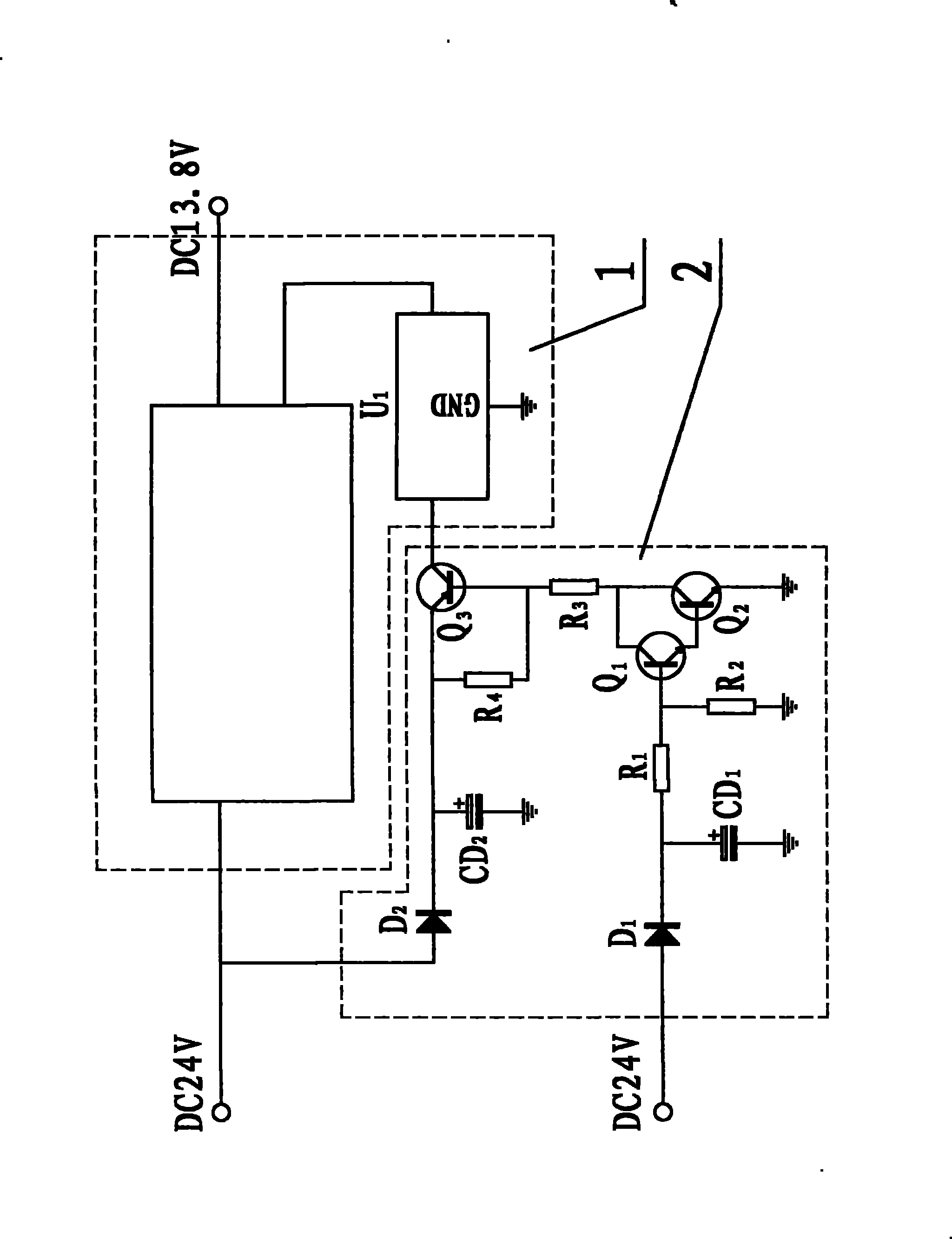
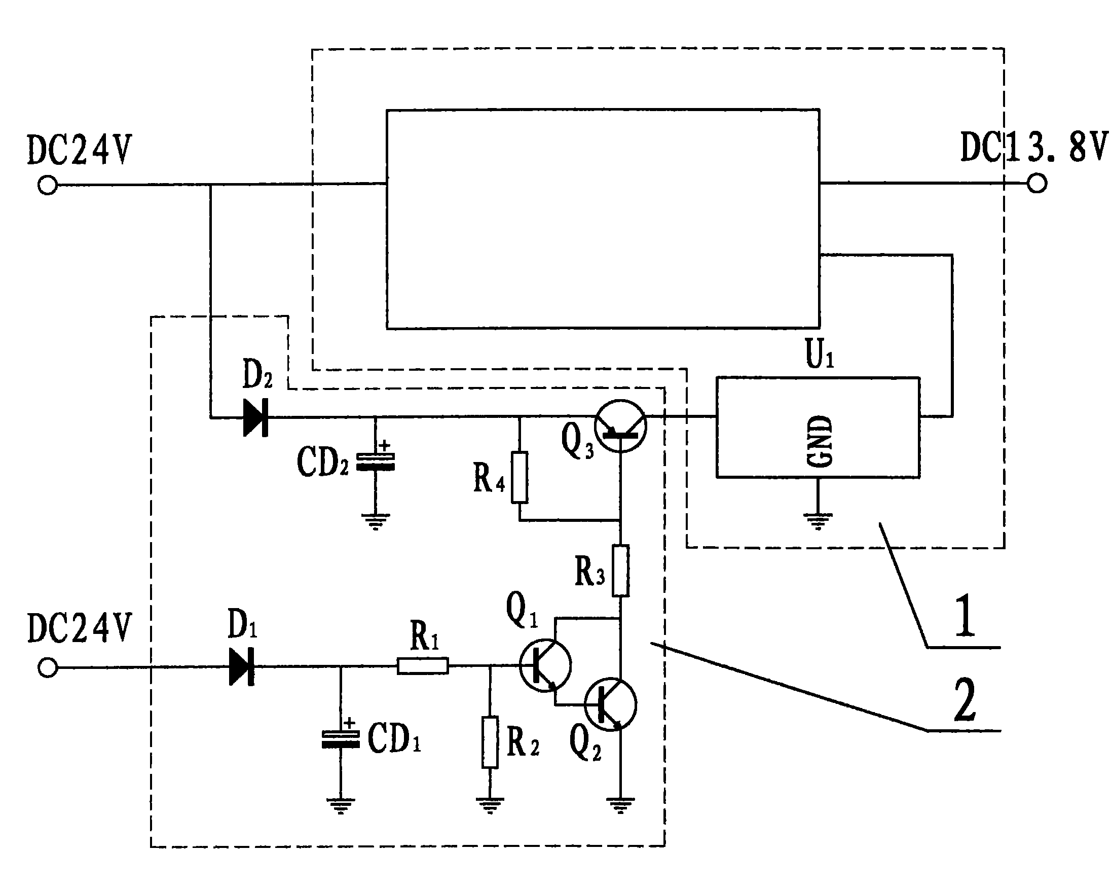
The invention discloses a vehicle power supply time-delay device comprising a power converter system and a control circuit, wherein the anode of a diode D2 of the control circuit is connected with a power supply +24V, and the cathode of the diode D2 is connected with the anode of a capacitor CD2, one end of a resistor R4 and the emitting electrode of an audion Q3; the collecting electrode of the audion Q3 is connected with a stabilized-voltage integrated circuit, and the base electrode of the audion Q3 is connected with the other end of the resistor R4; one end of a resistor R3 is connected with the base electrode of the audion Q3, and the other end is connected with the collecting electrodes of an audion Q2 and an audion Q1; the emitting electrode of the audion Q1 is connected with the base electrode of the audion Q2; one end of a resistor R2 is connected with the base electrode of the audion Q1 and one end of a resistor R1; the other end of the resistor R1 is connected with the anode of a capacitor CD1 and the cathode of a diode D1; the anode of the diode D1 is connected with the vehicle power supply +24V; and the cathode of the capacitor CD2, the cathode of the capacitor CD1, the other end of the resistor R2 and the emitting electrode of the audion Q2 are all earthed.
Description
[0001] Technical field [0002] The invention relates to a vehicle power supply delay device. Background technique [0003] Existing vehicles, such as passenger cars, generally contain engine electronic control devices, also known as engine controllers (ECUs), and the power supply of the controllers (ECUs) is provided by a power converter system. The input end of the power converter system is connected with the vehicle battery, and its output end is connected with the engine controller (ECU). The power converter system contains a voltage stabilizing integrated circuit. When the circuit supplies power to the system, the power converter system starts to work. After the vehicle is parked, it takes about 20 seconds for the electronic module data storage of the engine controller (ECU), and the vehicle battery of the existing vehicle has been supplying power to the engine controller (ECU) through the power converter system. In fact, the electronic module data storage of the engine...
Claims
Login to View More Application Information
Patent Timeline
 Patent Type & Authority Patents(China)
IPC IPC(8): G05B11/01H03K17/60B60R16/02
Inventor 谷正
Owner 谷正
Features
- R&D
- Intellectual Property
- Life Sciences
- Materials
- Tech Scout
- Unparalleled Data Quality
- Higher Quality Content
- 60% Fewer Hallucinations
Learn More Browse by: Latest US Patents, China's latest patents, Technical Efficacy Thesaurus, Application Domain, Technology Topic, Popular Technical Reports.
© 2025 PatSnap. All rights reserved.Legal|Privacy policy|Modern Slavery Act Transparency Statement|Sitemap|About US| Contact US: help@patsnap.com


