Fuel cell system

一种燃料电池系统、燃料电池的技术,应用在燃料电池、燃料电池助剂、电路等方向

Active Publication Date: 2009-09-30
TOYOTA JIDOSHA KK
View PDF4 Cites 0 Cited by
  • Summary
  • Abstract
  • Description
  • Claims
  • Application Information

AI Technical Summary

Problems solved by technology

Therefore, there is a possibility that the same disadvantage as that of the discharge valve described in Japanese Patent Application Laid-Open No. 2006-32134 may occur.

Method used


Image

  • Fuel cell system
  • Fuel cell system
  • Fuel cell system

Examples


Embodiment Construction

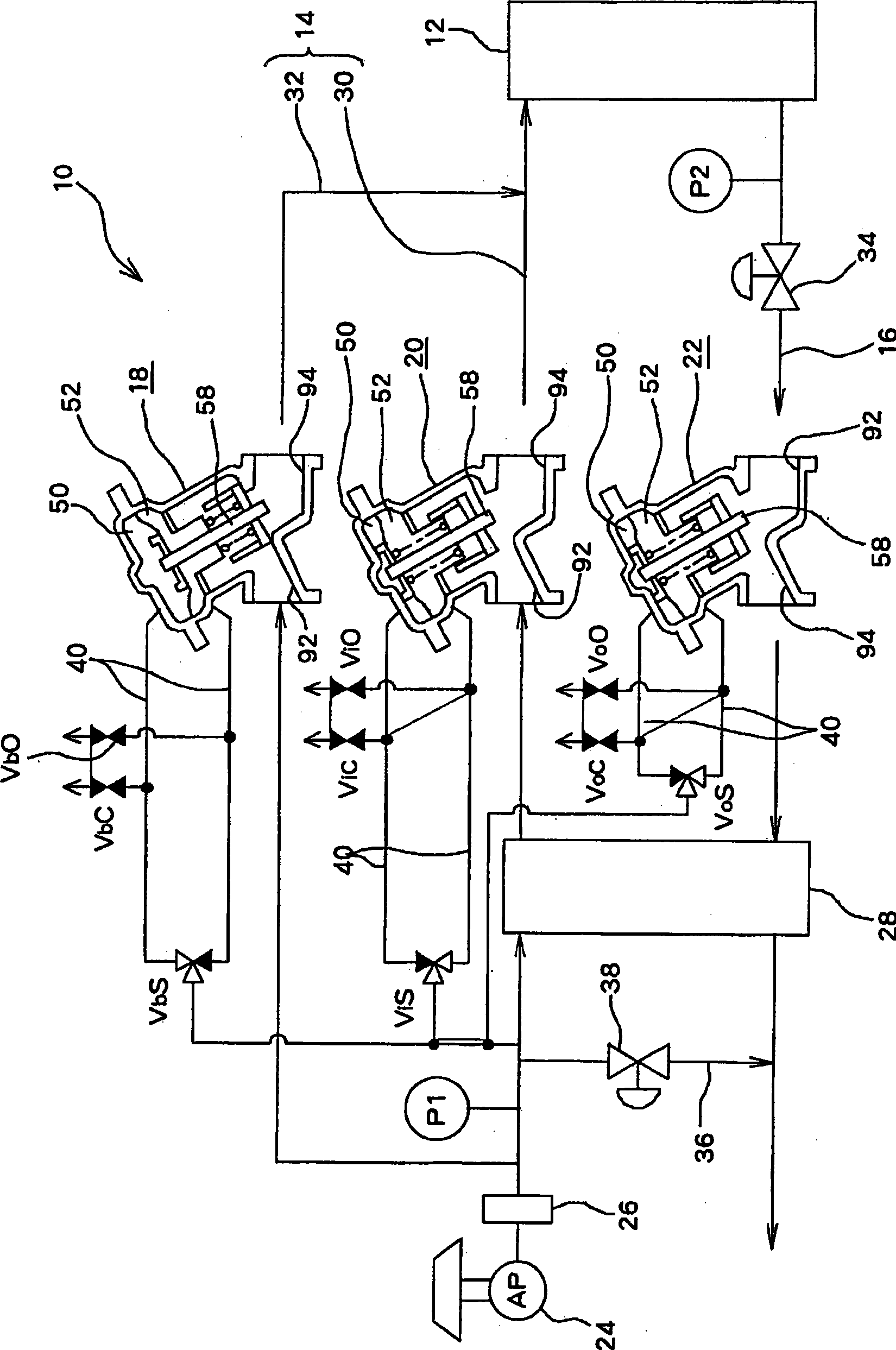
[0028] Hereinafter, an example of embodiment of the present invention will be described based on the drawings. From Figure 1 to Figure 2 Indicates this embodiment, figure 1 It is a schematic configuration diagram of the fuel cell system of this embodiment. The fuel cell system 10 has: a fuel cell stack 12 ; an oxidizing gas supply flow path 14 and an oxidizing gas system discharge flow path 16 ; a humidifier bypass valve 18 ; an inlet shutoff valve 20 ; and an outlet shutoff valve 22 .

[0029] The fuel cell stack 12 generates electricity by the electrochemical reaction of oxygen and hydrogen. That is, by supplying hydrogen as a fuel gas and air as an oxidizing gas to the fuel cell stack 12, oxygen and hydrogen electrochemically react in a plurality of fuel cell cells not shown in the fuel cell stack 12 to obtain electrical energy. . A fuel cell has, for example, a membrane-electrode assembly in which an electrolyte membrane is sandwiched between an anode-side electrode a...


PUM


Abstract

An outlet shutoff valve (22) where pressing surfaces (A, B), which press against each other, of a valve body (58) and a valve seat (80) are tilted relative to the vertical direction and where a drive shaft (60) can be driven in a direction tilted relative to the vertical direction. In the outlet shutoff valve (22), the pressing surfaces (A, B) are set high in the upstream side of gas flowing in a flow path forming pressure chamber (56), where the gas flows, and low in the downstream side.

Description

technical field [0001] The present invention relates to a fuel cell system comprising: a fuel cell for generating electricity through an electrochemical reaction of an oxidizing gas and a fuel gas; Cut or connect. Background technique [0002] The fuel cell system has: a fuel cell that generates electricity by electrochemical reaction of a reaction gas of a fuel gas and an oxidizing gas; a gas supply flow path for supplying a reaction gas to the fuel cell; and a gas discharge flow for discharging the reaction gas from the fuel cell. road. It is also conceivable to provide a fuel cell on-off valve corresponding to the fluid control valve on such a gas supply flow path and a gas discharge flow path. [0003] For example, an on-off valve for a fuel cell described in Japanese Patent Application Laid-Open No. 2004-183713 has a valve body provided with a column, and can shut off or connect the inside of the gas flow path by axial displacement of the column. In this on-off valve...

Claims


Application Information

Patent Timeline
Patent Type & Authority Applications(China)
IPC IPC(8): H01M8/04F16K31/126
CPCH01M8/04089F16K31/1262Y02E60/50
Inventor 竹下昌宏
Owner TOYOTA JIDOSHA KK
Why Eureka
Try Eureka