

Method and apparatus of friction welding
A technology of friction welding and welding parts, which is applied in welding equipment, high-frequency current welding equipment, non-electric welding equipment, etc., and can solve problems such as ugly appearance
- Summary
- Abstract
- Description
- Claims
- Application Information
AI Technical Summary
Problems solved by technology
Method used
Image

Examples
Embodiment Construction
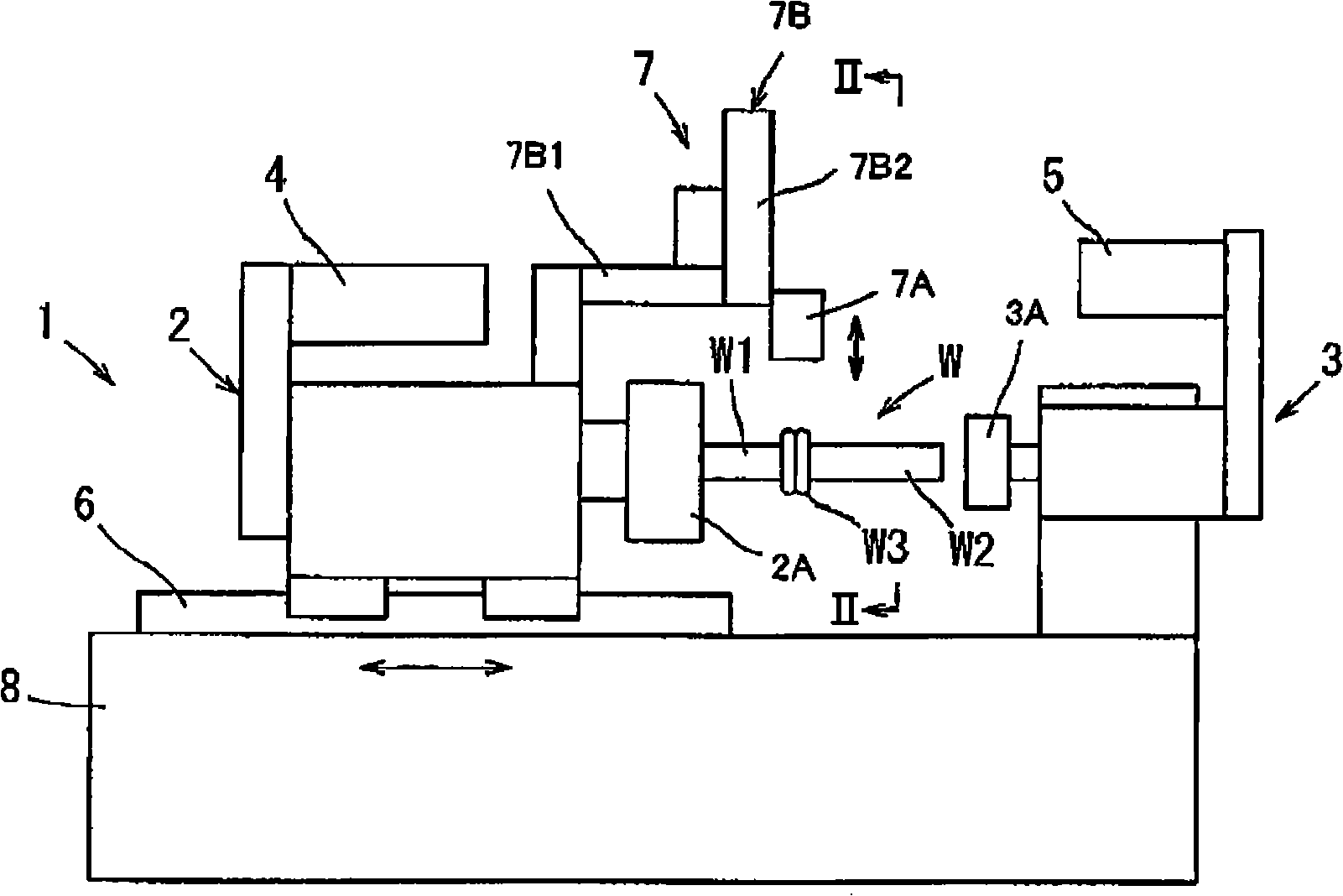
[0016] The following will refer to Figures 1 to 8 Embodiments of the present invention are described. refer to figure 1 , the friction welding device 1 includes a base 8 , a first holder 2 (spindle unit) and a second holder 3 . A guide 6 is installed at a position adjacent to the left end of the pedestal 8 . The first holder 2 is slidably installed with respect to the guide 6 and moved along the guide 6 by a thrust motor (not shown). The second holder 3 is immovably mounted on the pedestal 8 at its right end. The first holder 2 has a chuck 2A to detachably hold a round bar-shaped first workpiece W1. On the first holder 2 is mounted a motor 4 operable to rotate the chuck 2A around its axis. Also, the second holder 3 has a chuck 3A to detachably hold a round bar-shaped second workpiece W2. On the second holder 3 is mounted a motor 5 operable to rotate the chuck 3A around its axis.
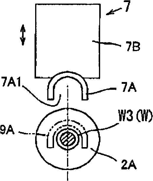
[0017] A high-frequency induction heater 7 is mounted on the first holder 2 to inductivel...
PUM
 Abstract
Description
Claims
Application Information