Fixing device and floor type lamp provided with same

A fixed device and floor-standing technology, which is applied to the parts of lighting devices, light source fixing, lighting devices, etc., can solve the problems of falling off lamp rods, unstable lamp rods, swaying and other problems, and achieve the effect of convenient installation and operation.

Inactive Publication Date: 2009-10-07
OCEANS KING LIGHTING SCI&TECH CO LTD
View PDF0 Cites 9 Cited by
  • Summary
  • Abstract
  • Description
  • Claims
  • Application Information

AI Technical Summary

Problems solved by technology

In the existing floor lamps, including the lamp base and the lamp pole, the connection between the lamp pole and the lamp base is usually detachable connection, that is, a jack is set on the lamp base, and the lower end of the lamp pole is inserted into the jack. With this connection method, since the joint length between the lamp pole and the lamp holder is short, and the matching precision between the jack and the lamp pole is not high, there is a gap, so the lamp pole cannot be well fixed in the socket, resulting in the lamp pole being in the socket. In the process of use, it is easy to appear unstable phenome

Method used


Image

  • Fixing device and floor type lamp provided with same
  • Fixing device and floor type lamp provided with same
  • Fixing device and floor type lamp provided with same

Examples


Embodiment 1

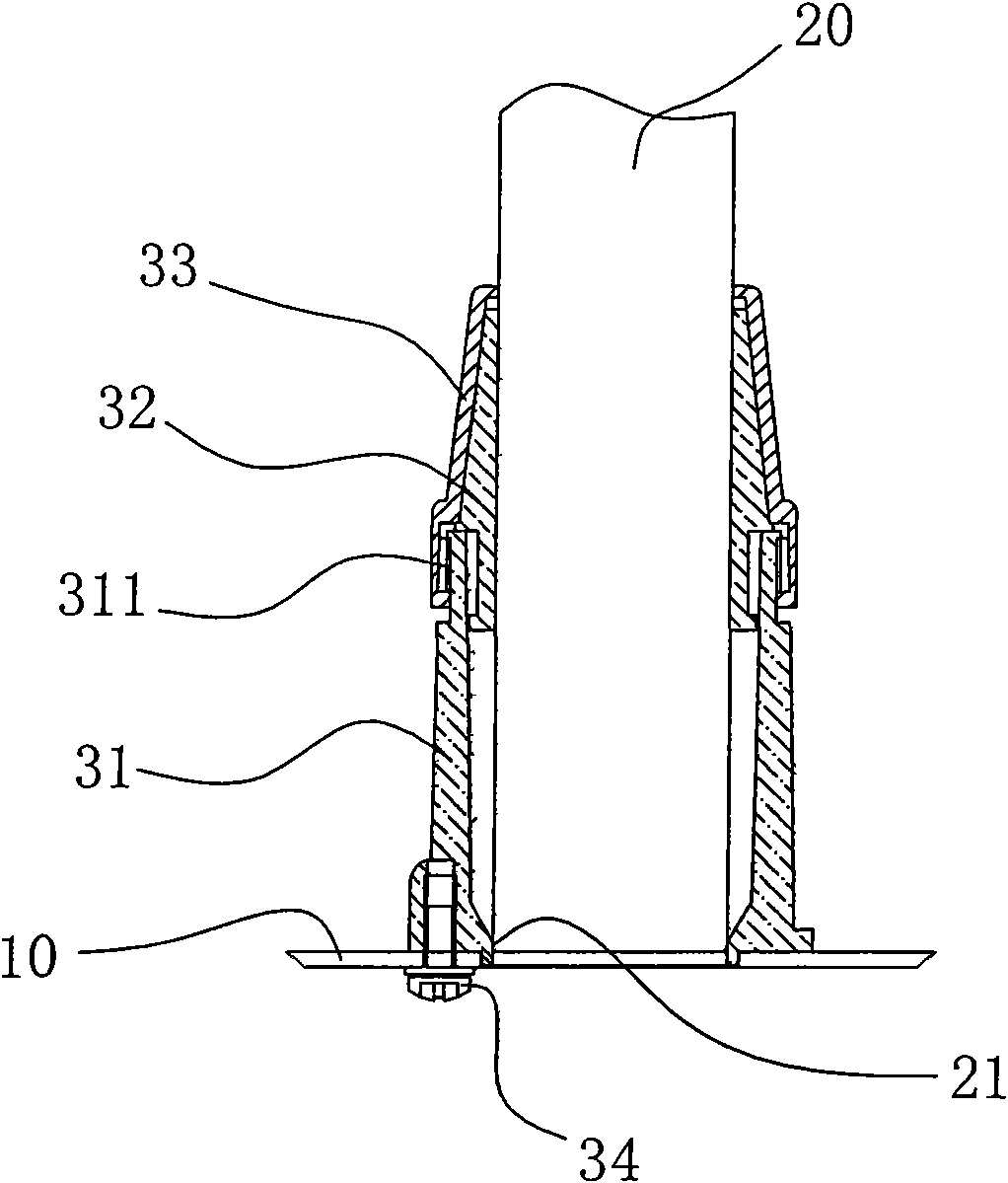
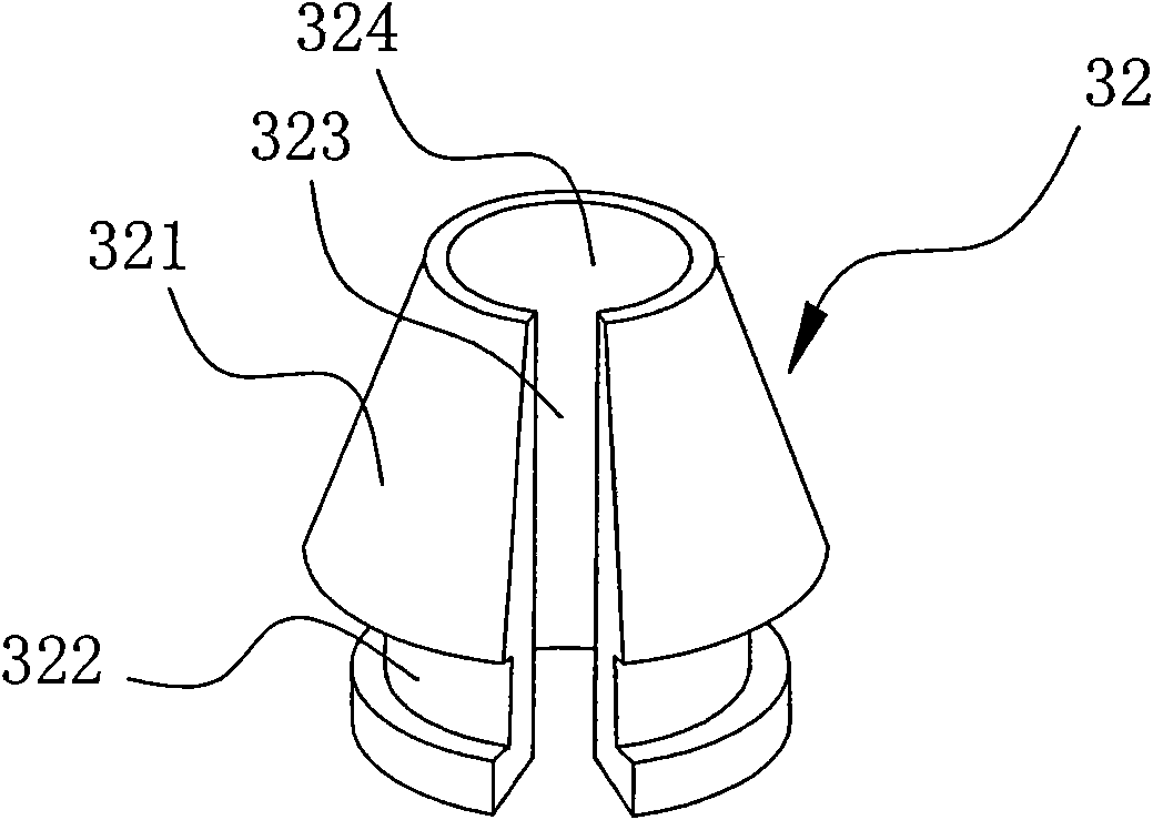
[0022] like figure 1 As shown, the fixed connection structure includes a plate-shaped fixing piece 10, a cylindrical fixed piece 20, and a fixing device 30 that vertically fixes the fixed piece 20 on the fixing piece 10, wherein the fixing device 30 includes a cylindrical fixing seat 31. Locking claw sleeve 32, locking nut 33, a hole is opened on the top of the fixing base 31, the lower part is vertically fixedly connected with the fixing part 10 through a screw 34, and a thread 311 is provided on the outer side wall of the upper part, and the lower end of the fixed part 20 is inserted into the sleeve In the middle hole of the fixing seat 31, the locking claw cover 32 is cylindrical and is set on the fixed part on the upper part of the fixing seat 31. Threaded connection, the surface where the locking claw sleeve 32 cooperates with the inner wall surface of the locking nut 32 is a conical surface. In this fixed connection structure, when the fixed part 10 is fixed, the cylind...

Embodiment 2

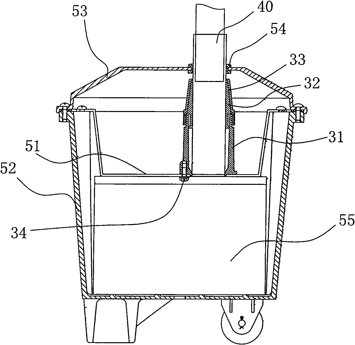
[0027] like image 3 As shown, the floor lamp includes a lamp base assembly, a lamp pole 40, and a fixing device for fixing the lamp pole. The upper part of the lamp pole 40 is connected with a lamp head (the lamp head is not shown in the figure). The lamp holder assembly includes a box body 52, a box cover 53, and a base plate 51. The base plate 51 is fixedly installed in the box body 52, and its outer edge is fixedly connected with the top of the side wall of the box body 52, and forms a box that can be used to place a power supply device. space 55, the lamp pole 40 adopts the fixed connection structure in Embodiment 1 and is vertically fixed on the base plate 51 through the fixing device composed of the fixing seat 31, the locking claw sleeve 32, and the locking nut 33, wherein the fixed connection structure is It has been described in detail in Embodiment 1 and will not be repeated here.

[0028] In this example, if image 3 As shown, the box cover 53 is fixedly connect...


PUM


Abstract

The invention relates to a fixing device comprising a fixed seat, a locking jaw sleeve and a locking nut, wherein a hole is arranged at the top of the fixed seat, and screw threads are arranged on the outer side wall of the upper part of the fixed seat; the locking jaw sleeve is in a cylinder shape and is arranged at the top of the fixed seat, the middle hole of the locking jaw sleeve is communicated with the hole arranged at the top of the fixed seat; the locking nut is sleeved outside the locking jaw sleeve and screwed with the upper segment of the fixed seat; the surface of the locking jaw sleeve, which is matched with the inner wall surface of the locking nut, is a cone-shaped surface; and a hole which is communicated with the middle hole of the locking jaw sleeve is arranged on the top surface of the locking nut. Simultaneously, the invention also provides a floor type lamp which applies the fixing device for fixedly connecting a lamp rod and a lamp seat. In the invention, the fixing device is a detachable connection structure, can connect a fixing piece and a fixed piece stably and is convenient for installation.

Description

technical field [0001] The invention relates to a fixed connection structure, more specifically, to a fixing device and a floor lamp with the device. Background technique [0002] In the existing connection structure, especially when a columnar member is vertically fixedly connected to a planar plate and is detachably connected, the usual practice is to set holes on the plate, and insert the columnar member into the hole. In, for example, the fixed connection of the luminaire pole to the lampholder in floor-standing luminaires. In the existing floor lamps, including the lamp base and the lamp pole, the connection between the lamp pole and the lamp base is usually detachable connection, that is, a jack is set on the lamp base, and the lower end of the lamp pole is inserted into the jack. With this connection method, since the joint length between the lamp pole and the lamp holder is short, and the matching precision between the jack and the lamp pole is not high, there is a ...

Claims


Application Information

Patent Timeline
IPC IPC(8): F21V17/10F16B7/06F21S6/00F21V21/06
Inventor 周明杰张玉泉
Owner OCEANS KING LIGHTING SCI&TECH CO LTD
Why Eureka
Try Eureka