
Die clamp

A fixture and mold technology, which is used in the field of fixtures for fixing molds, especially upper molds of bending machines, can solve the problems of very high requirements for spherical bolt locking accuracy, difficulty in implementation, poor adaptability, etc., and achieves easy installation and operation. , Simple structure, strong adaptability

Inactive Publication Date: 2009-04-29
米路加(上海)板金机械技术开发有限公司
View PDF1 Cites 7 Cited by
  • Summary
  • Abstract
  • Description
  • Claims
  • Application Information

AI Technical Summary

Problems solved by technology

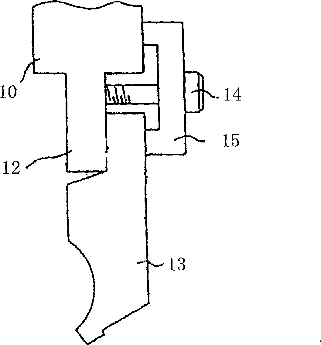
[0008] but, Figure 2A and 2B The fixture shown is still flawed
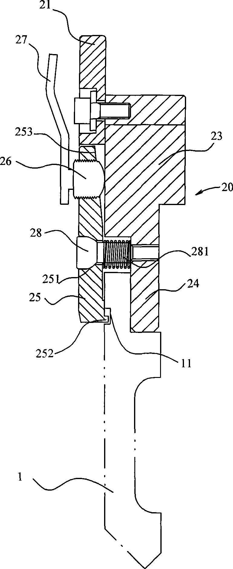
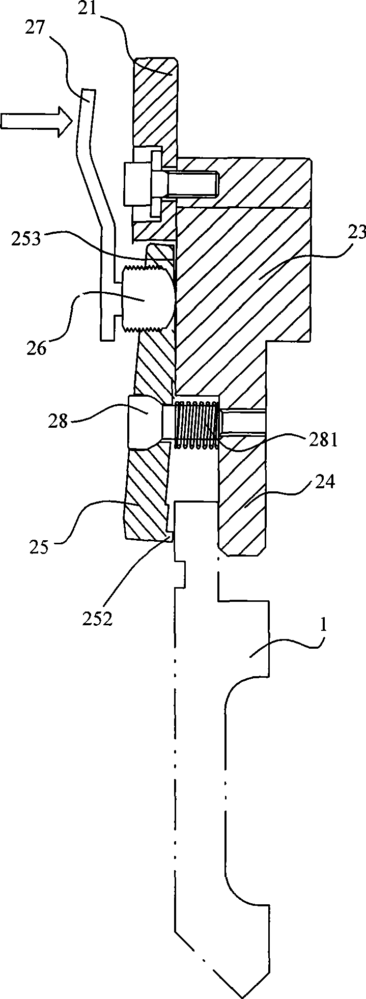
Since the contact surfaces between the heads of the mounting bolts 28 and the clamping parts 25 are all spherical surfaces, when a plurality of mounting bolts such as Figure 2C When the shown mounting bolts 28a and 28b are locked into the support plate 27, the clamping surface of the clamping member 25 will be different due to the different tightening forces applied by the operator. Figure 2C In the horizontal direction relative to the support surface of the support plate 27, the angle a is produced, which cannot be fully contacted with the mold 1 to clamp it, such as Figure 2C shown
Therefore, this kind of fixture has very high requirements on the locking accuracy of spherical bolts, and it is very difficult to realize
In addition, the anti-drop protrusion 252 protruding from the inner side of the lower end of the clamping member 25 determines that this kind of clamp can only clamp molds with anti-drop grooves, so the adaptability is very poor

Method used


Image

  • Die clamp
  • Die clamp
  • Die clamp

Examples


Embodiment Construction

[0037] The present invention will be further described below in conjunction with accompanying drawing and embodiment:

[0038] 3A and 3B show the structure of the mold jig of the first embodiment of the present invention. As shown in the figure, the fixture includes a clamping body 30 detachably mounted on the bottom of the upper workbench 2 through a mounting plate 31. The clamping body 30 includes an upper thick-walled clamping body 33 and a vertical direction along the lower end of the clamping body 33. A thin-walled support plate 34 extending downward. The clamping body 33 is fixed to the mounting plate 31 by a plurality of bolts 311 on the upper part and a plurality of bolts 341 on the lower part, so that it can be installed on the lower part of the upper workbench 2 through the mounting plate 31 . As shown in Figure 3B, the mounting plate 31 is in contact with the lower front side of the upper workbench, and the jaws 22 are fastened on the upper workbench 2 by fastening...


PUM


Abstract

The invention discloses a mould clamp, which comprises a clamping body installed at the lower part of an upper worktable detachably by an installation plate and a clamping part being capable of swinging relative to the clamping body; by virtue of the clamping force generated by a clamping force regulating device on the clamping part, the mould clamp tightly clamps a mould between the clamping part and a support plate extended out of the lower part of the clamping body, wherein, the inner side of the clamping part opposite to the support plate is provided with a cushion block so as to provide support for the clamping part to swing relative to the clamping body. The novel mould clamp utilizes the cushion block arranged at the inner side of the clamping part for providing support for the clamping part to swing relative to the clamping body instead of adopting a spherical bolt in the prior art, therefore, the mould clamp eliminates the problem of the difficult controlling of the locking precision of the spherical bolt and has the advantages of simple structure, easy installation and operation, and firmly clamping.

Description

technical field [0001] The present invention relates to a fixing device, more specifically, to a clamp for fixing a mold, especially an upper mold of a bending machine. Background technique [0002] The bending machine is used to bend the plate-shaped workpiece into various required shapes through the mold. Usually, the bending machine is equipped with upper and lower worktables facing up and down. The upper and lower worktables are respectively equipped with an upper die (that is, a punch) and a lower die. When the lower mold is closed, the workpiece located between the upper mold and the lower mold is bent, and the shape of the bend depends on the specific design of the upper and lower molds. [0003] The upper mold of the bending machine is generally fixed on the lower part of the upper worktable by a clamp, so that different upper molds can be replaced according to the required workpiece shape. Because the mold itself is relatively heavy, and the precision requirements...

Claims


Application Information

Patent Timeline
IPC IPC(8): B21D37/04B21D37/12
CPCB21D5/0236
Inventor 土山雄司中村典夫
Owner 米路加(上海)板金机械技术开发有限公司
Learn More