Belt conveyor

A technology of belt conveyors and conveyor belts, applied in conveyors, transportation and packaging, etc., can solve the problems of inability to generate large tension, high piston strength, and high failure rate, and achieve the elimination of unbalanced force and installation accuracy Low requirements and the effect of reducing space restrictions

Active Publication Date: 2011-04-13
CHINA ENFI ENGINEERING CORPORATION
View PDF1 Cites 3 Cited by
  • Summary
  • Abstract
  • Description
  • Claims
  • Application Information

AI Technical Summary

Problems solved by technology

[0005] However, in the above-mentioned patent application, since a hydraulic cylinder is used to generate tension, the range of tension is small and large tension cannot be generated.
For example, in mining, the force of the material in the intermediate silo on the conveyor belt can reach tens to tens of tons. Therefore, the required tension cannot be generated with a hydraulic cylinder.
In addition, under poor working conditions, such as an environment with a lot of dust, the components of the hydraulic system are prone to failure
At the same time, the control of the hydraulic system is very complicated, the tension adjustment is complicated, and the tension is unstable, which leads to the complex structure of the entire tension device, which leads to increased costs and high failure rates
[0006] Secondly, for the use of hydraulic cylinders and hydraulic valves, the strength of hydraulic cylinders such as pistons is required to be very large. A failure of a hydraulic valve may cause the entire tensioning device to fail to generate tension. Therefore, the reliability of hydraulic cylinders and hydraulic valves is very high. High, high production cost, frequent maintenance
[0007] In addition, the hydraulic system used in the above patent application requires a separate hydraulic station. During the operation of the conveyor, the hydraulic system needs to work all the time, so the cost is high
Moreover, a large space is required for the hydraulic station to be arranged behind the conveyor, resulting in a very large space occupied by the entire tensioning device

Method used


Image

  • Belt conveyor
  • Belt conveyor
  • Belt conveyor

Examples


Embodiment Construction

[0039] Embodiments of the present invention are described in detail below, examples of which are shown in the drawings, wherein the same or similar reference numerals designate the same or similar elements or elements having the same or similar functions throughout. The embodiments described below by referring to the figures are exemplary only for explaining the present invention and should not be construed as limiting the present invention.

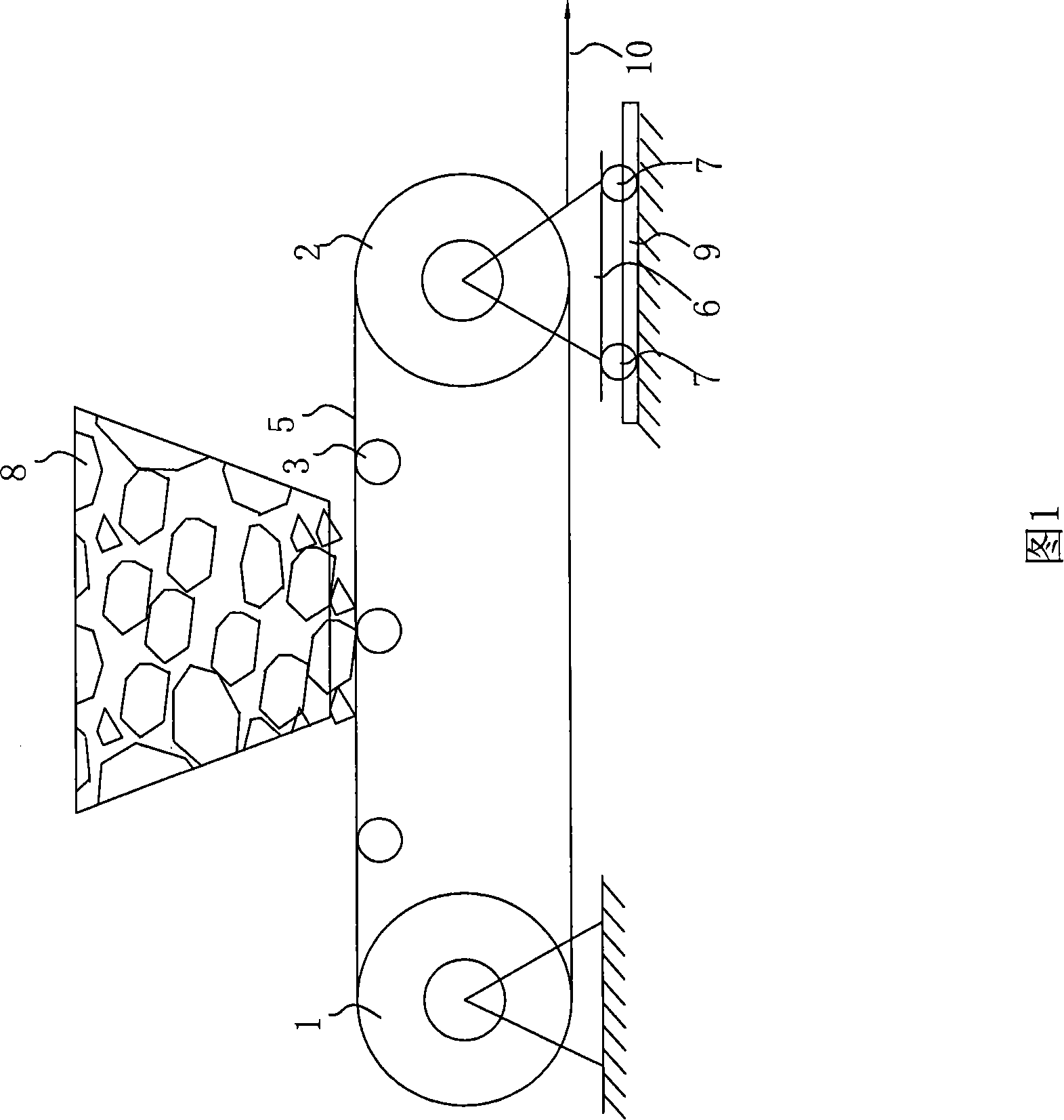
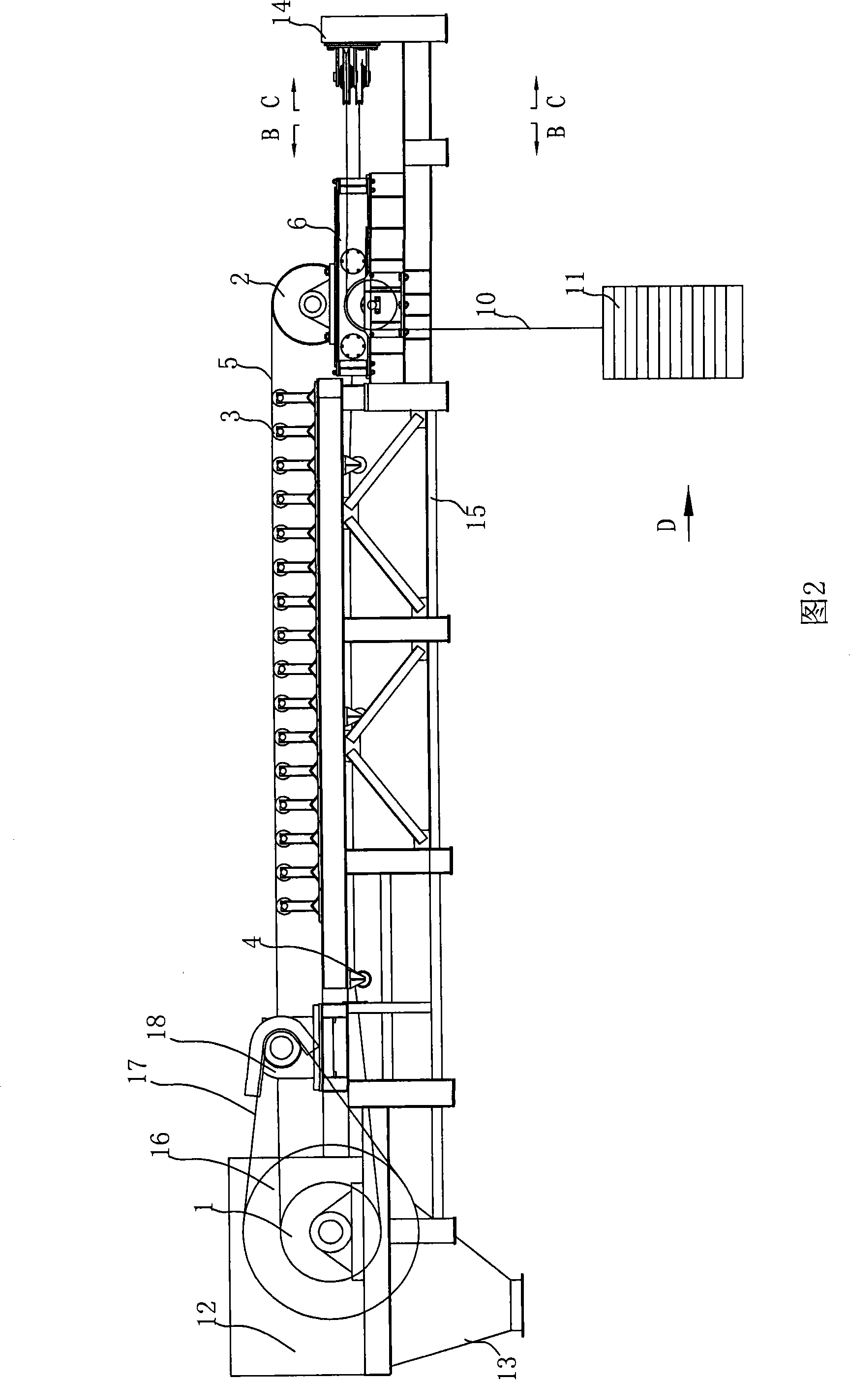
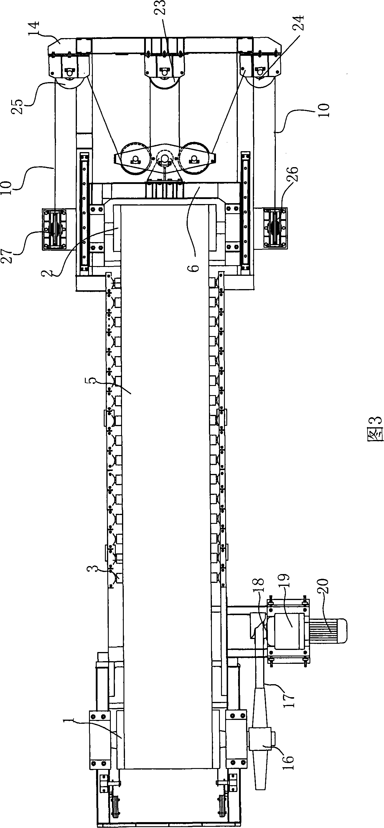
[0040] For the convenience of description, in the present invention, one side of the driving drum of the belt conveyor is defined as the front, and one side of the diverting drum is defined as the rear, that is, the direction of material movement on the belt conveyor is the forward direction, and The opposite direction is the backward direction. In addition, the direction in which the redirection roller and the movable support move is defined as the longitudinal direction, and the direction perpendicular thereto is the transverse directi...


PUM


Abstract

The invention relates to a belt conveyor, which comprises a driving roller, a diverted roller, a conveyor belt, a drive device and a tension device. The tension device comprises a movable bracket, a diverted rollers which is arranged on the movable bracket and is suitable for installing the belt conveyor, fixed pedestals fixedly arranged on two sides and the rear of the movable bracket, a first diverted pulley and a second diverted pulley which are horizontally arranged on the fixed pedestals along the axial lines and positioned on the two sides of the moveable bracket, a first movable pulleywhich is vertically arranged on the rear end face of the movable bracket along the axial line, a first fixed pulley and a second fixed pulley which are vertically arranged on the fixed pedestals alongthe axial lines, and a rope. A first end of the rope is connected with a balance weight; and a second end of the rope sequentially rounds the first diverted pulley, the first fixed pulley, the firstmovable pulley, the second fixed pulley and the second diverted pulley and is connected with the balance weight. The tension device of the belt conveyor has small occupied space, wide and stable tension range, and simple structure.

Description

technical field [0001] The invention relates to a belt conveyor, in particular to a belt conveyor with a tensioning device capable of reducing the space required for installation, having a large and stable tension range and a simple structure. Background technique [0002] Belt conveyors are widely used in mining, metallurgy and other fields. The tensioning device is an important part of the belt conveyor. The tensioning device is used to ensure sufficient tension of the conveyor belt, and to ensure sufficient friction between the drive rollers during the startup, braking, and normal operation of the conveyor. Prevent slipping etc. In addition, the sag of the conveyor belt is limited to prevent material from falling off the conveyor belt. [0003] Usually the form of the tensioning device is a screw tensioning device, a vertical weight tensioning device, etc. These tensioning devices have their limitations. For example, the screw tensioning device is only suitable for sm...

Claims


Application Information

Patent Timeline
Patent Type & Authority Patents(China)
IPC IPC(8): B65G23/44B65G15/00
Inventor 佟康令郝朋越邱杰敏
Owner CHINA ENFI ENGINEERING CORPORATION
Why Eureka
Try Eureka