
Rotary drilling rig and vehicle center of gravity control method and system thereof

A technology of rotary drilling rig and center of gravity control, applied in drilling equipment and methods, electrical program control, program control in sequence/logic controller, etc., can solve problems such as unstable center of gravity and rollover of the whole vehicle, and achieve counterweight Lightweight, economical and stable

Active Publication Date: 2015-12-02
SHANGHAI ZOOMLION HEAVY IND PILING MACHINERYCO +1
View PDF5 Cites 0 Cited by
  • Summary
  • Abstract
  • Description
  • Claims
  • Application Information

AI Technical Summary

Problems solved by technology

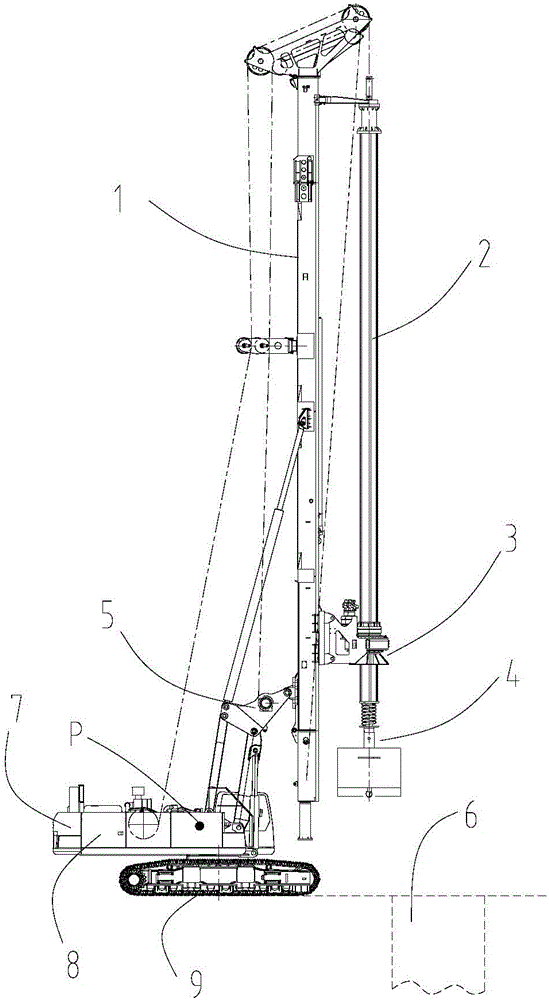
Since the working device of the rotary drilling rig, that is, the mast 1, the drill pipe 2, the power head 3 and the drilling tool 4, etc. are moving, the horizontal distance between them and the upper vehicle 8 is constantly changing, and the range of motion is large, and the counterweight 7. The position relative to the vehicle is fixed, which will cause the center of gravity of the vehicle to be unstable, and there is a hidden danger of overturning under extreme conditions or careless operation

Method used


Image

  • Rotary drilling rig and vehicle center of gravity control method and system thereof
  • Rotary drilling rig and vehicle center of gravity control method and system thereof
  • Rotary drilling rig and vehicle center of gravity control method and system thereof

Examples


Embodiment Construction

[0031] Specific embodiments of the present invention will be described in detail below in conjunction with the accompanying drawings. It should be understood that the specific embodiments described here are only used to illustrate and explain the present invention, and are not intended to limit the present invention.

[0032] In the present invention, in the case of no contrary description, the used orientation words such as "front and back" are words used to describe the mutual positional relationship between the components under the normal working state of the rotary drilling rig, wherein, with Figure 4 The direction shown is the reference direction, Figure 4 In the rotary drilling rig, the direction of the working device is "front", and the direction of the counterweight is "rear".

[0033] see Figure 4 and Figure 5 , generally, a rotary drilling rig mainly includes a chassis 70, an upper car 60 and a working device, wherein the working device mainly includes a mast ...


PUM


Abstract

The invention provides a rotary drilling rig and a gravity center control method and system of an entire machine. The rotary drilling rig comprises an upper machine (60), a working device at the front end of the upper machine (60) and a counterweight (61) at the rear end of the upper machine (60), wherein the working device comprises a derricking cylinder (52) and a movable arm (51). The gravity center control method of the entire machine includes: acquiring torque between the working device and the gravity center of the entire machine when the working device is in different working states; computing a target position of the counterweight (61) according to the torque; controlling the counterweight (61) to move to the target position. The rotary drilling rig and the gravity center control method and system of the entire machine have the advantages that stable controlling for the gravity center of the entire machine can be realized, and the controlling method is simple; among different types of the rotary drilling rigs, although the counterweights are different in weight, the counterweight (61) can be universalized by changing the position of the counterweight (61), so that the rotary drilling rig is better in stability and economical efficiency, and the counterweight (61) can be lighter.

Description

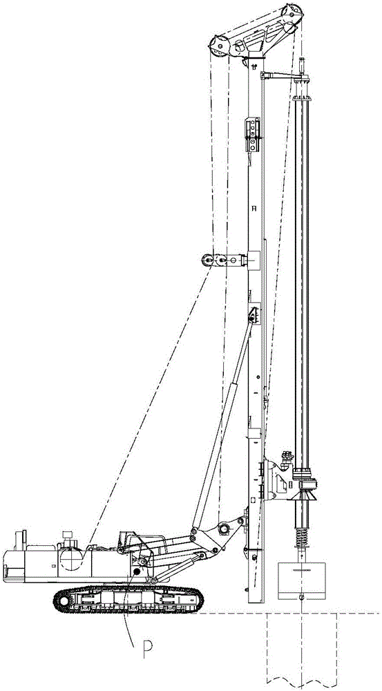
technical field [0001] The invention relates to the field of construction machinery, in particular to a rotary drilling rig and a method and system for controlling the center of gravity of the vehicle. Background technique [0002] Rotary drilling rig is the most common hole-forming equipment in foundation construction. It mainly includes chassis 9, upper vehicle 8 and working device. Among them, the working device mainly includes mast 1, drill pipe 2, power head 3 and drilling tool 4 , luffing mechanism 5, hoisting mechanism and other components. Please also see Figure 1-Figure 3 , Figure 1-Figure 3 It shows the three states that the rotary drilling rig is often in. The first state is the state where the working device is to be folded or unfolded, such as figure 1 As shown, the drill pipe 2, the mast 1 and the drilling tool 4 are in an upright state relative to the upper carriage 8, and are close to the upper carriage 8; the second state is the state where the working d...

Claims


Application Information

Patent Timeline
Patent Type & Authority Patents(China)
IPC IPC(8): E21B7/02G05B19/04
Inventor 苏晖
Owner SHANGHAI ZOOMLION HEAVY IND PILING MACHINERYCO
Learn More