
Solar cell and solar cell module using the same

A solar cell and electrode technology, applied in the field of solar cells, can solve the problem that sunlight cannot be absorbed

Inactive Publication Date: 2009-11-25
SAMSUNG ELECTRONICS CO LTD
View PDF8 Cites 6 Cited by
  • Summary
  • Abstract
  • Description
  • Claims
  • Application Information

AI Technical Summary

Problems solved by technology

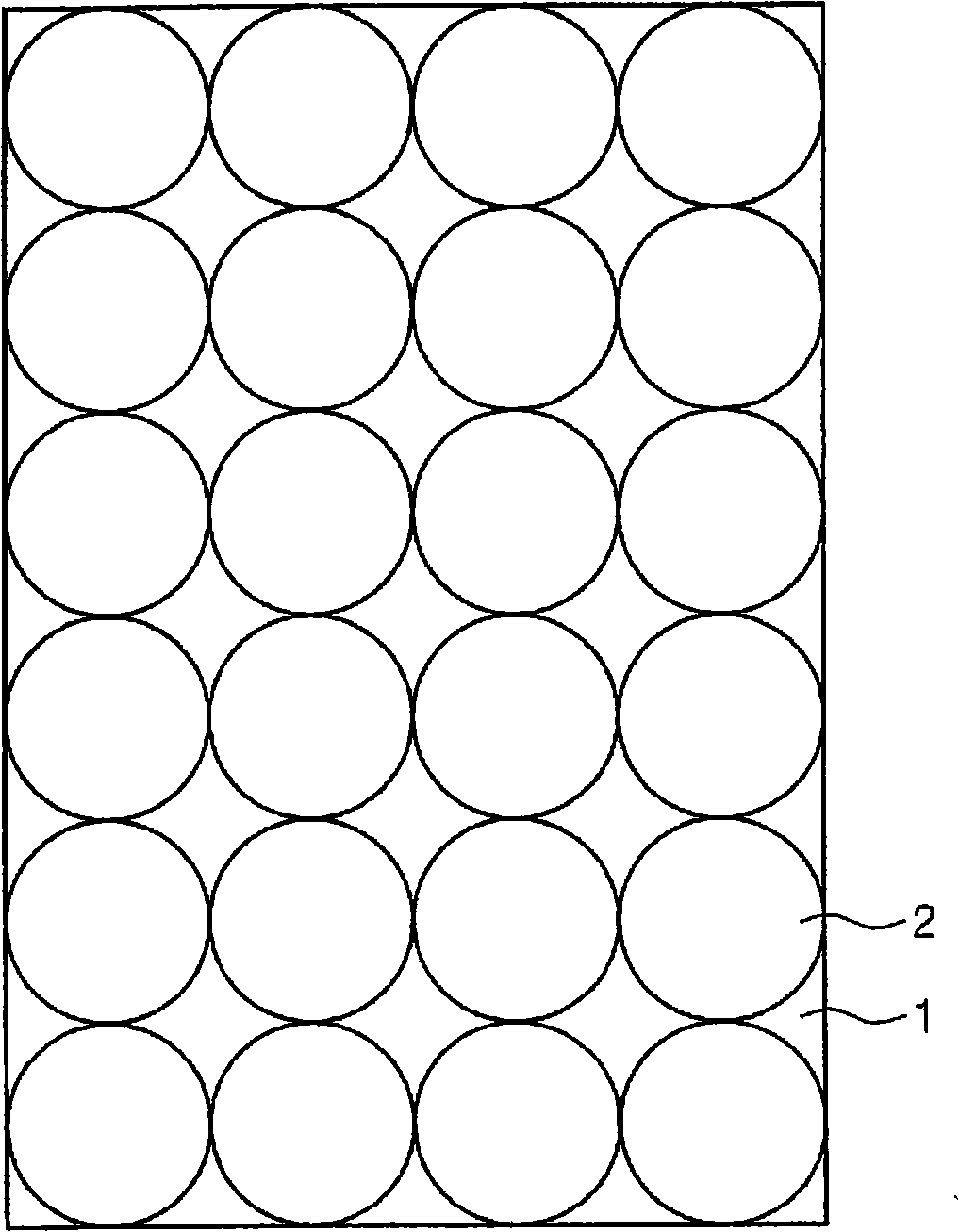
However, this arrangement of solar cells on the frame results in a dead area where sunlight cannot be absorbed due to the absence of solar cells

Method used


Image

  • Solar cell and solar cell module using the same
  • Solar cell and solar cell module using the same
  • Solar cell and solar cell module using the same

Examples


Embodiment Construction

[0028] The object, other objects, features and advantages of the present invention will be more easily understood by referring to the exemplary embodiments of the accompanying drawings. However, this invention may be embodied in different forms and should not be construed as limited to only the embodiments set forth herein. Rather, these embodiments are provided so that this disclosure will be thorough and complete, and will fully convey the scope of the invention to those skilled in the art.

[0029] In this specification, it will be understood that when an object is referred to as being "on" another object or substrate, it can be directly on the other object or substrate, or intervening objects may also be present. Also, in the drawings, the size of objects and regions are exaggerated for clarity of illustration. Also, although terms such as first, second and third are used to describe various objects in different embodiments of the present invention, the objects are not li...


PUM


Abstract

Provided is a solar cell module having improved energy efficiency. The solar cell module includes a frame, first solar cells arranged at the frame, and second solar cells smaller than the first solar cells. The second solar cells are disposed in regions surrounded by the first solar cells. The first solar cells have a substantially circular shape. The second solar cells have a rectangular shape, and each of the second solar cells is surrounded by four of the first solar cells.

Description

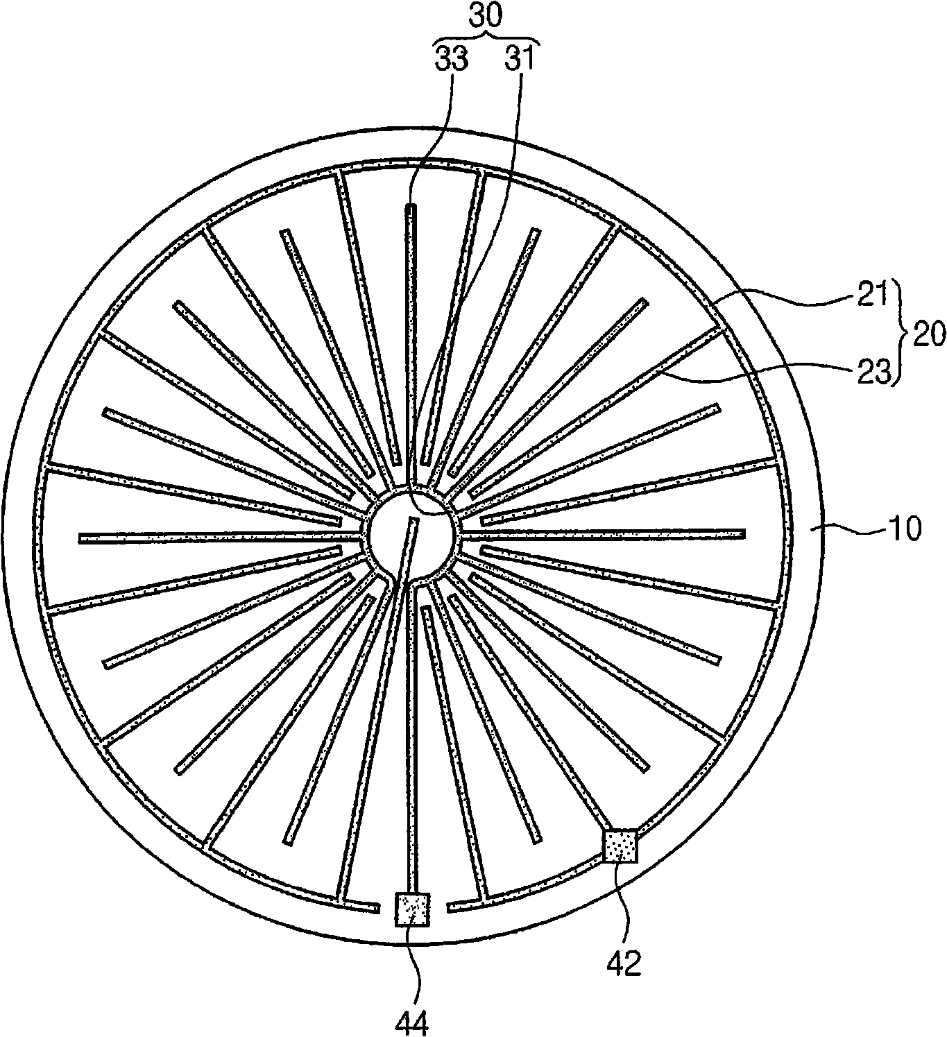
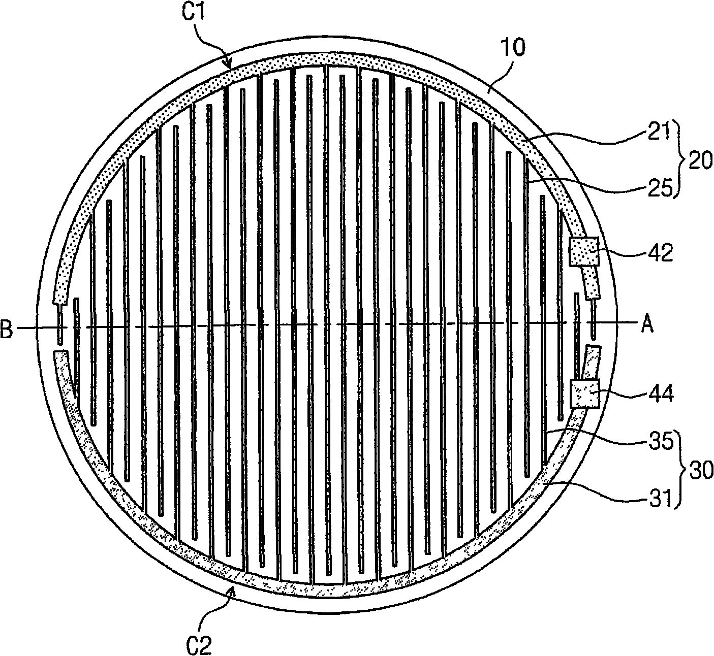
technical field [0001] The present invention relates to a solar cell, and more particularly, to a solar cell including an electrode on which sunlight is incident on a front surface and a solar cell module using the same. Background technique [0002] In a solar cell, the absorption of light leads to the generation of electron-hole pairs in the semiconductor, and the electric field formed at the P-N junction of the semiconductor moves the electrons to the N-type side of the semiconductor and the holes to the P-type side of the semiconductor, thereby generating current. [0003] Generally, at least one of a P-type electrode and an N-type electrode of a solar cell is disposed on the rear surface of the substrate. If the metal electrode covers the front surface of the substrate, the absorption of sunlight decreases in proportion to the area covered by the metal electrode. This is called shading loss. Solar cells can be formed using circular silicon wafers. refer to figure 1...

Claims


Application Information

Patent Timeline
IPC IPC(8): H01L31/042H01L31/06H01L31/0224H01L31/02H01L31/05H01L31/0352H01L31/04H01L31/0747
CPCH01L31/022425H01L31/022433Y02E10/50H01L31/05H01L31/042H01L31/0201H01L31/0508H01L31/02
Inventor 金允基李斗烈
Owner SAMSUNG ELECTRONICS CO LTD
Learn More