Harmonic-var comprehensive compensation system based on two-way dynamic reactive power compensation devices

A compensation device and comprehensive compensation technology, which is applied in the field of harmonic and reactive power comprehensive compensation systems, can solve the problems of not being able to adapt to fast response occasions, increase APF capacity, and aggravate APF burden, so as to reduce volume, reduce cost, and reduce The effect of compensating pressure

Inactive Publication Date: 2009-11-25
西安赛博电气有限责任公司
View PDF1 Cites 20 Cited by
  • Summary
  • Abstract
  • Description
  • Claims
  • Application Information

AI Technical Summary

Problems solved by technology

[0004] 1. The reactive capacity of TCR and MSC is the same as the maximum reactive capacity required to be compensated by the power grid, which makes the system huge
[0005] 2. The control element of TCR—thyristor is a semi-controlled device. Each thyristor is triggered and changes once in a power frequency cycle of grid voltage. According to the measurement, the fastest response time of this change is 10ms, and the response time of the whole system It is about 100ms, which cannot meet the needs of fast response occasions
[0006] 3. TCR generates a large amount of harmonic current during operation, which aggravates the burden of APF, increases the capacity of APF, and further increases the volume of the system

Method used


Image

  • Harmonic-var comprehensive compensation system based on two-way dynamic reactive power compensation devices
  • Harmonic-var comprehensive compensation system based on two-way dynamic reactive power compensation devices
  • Harmonic-var comprehensive compensation system based on two-way dynamic reactive power compensation devices

Examples


Embodiment Construction

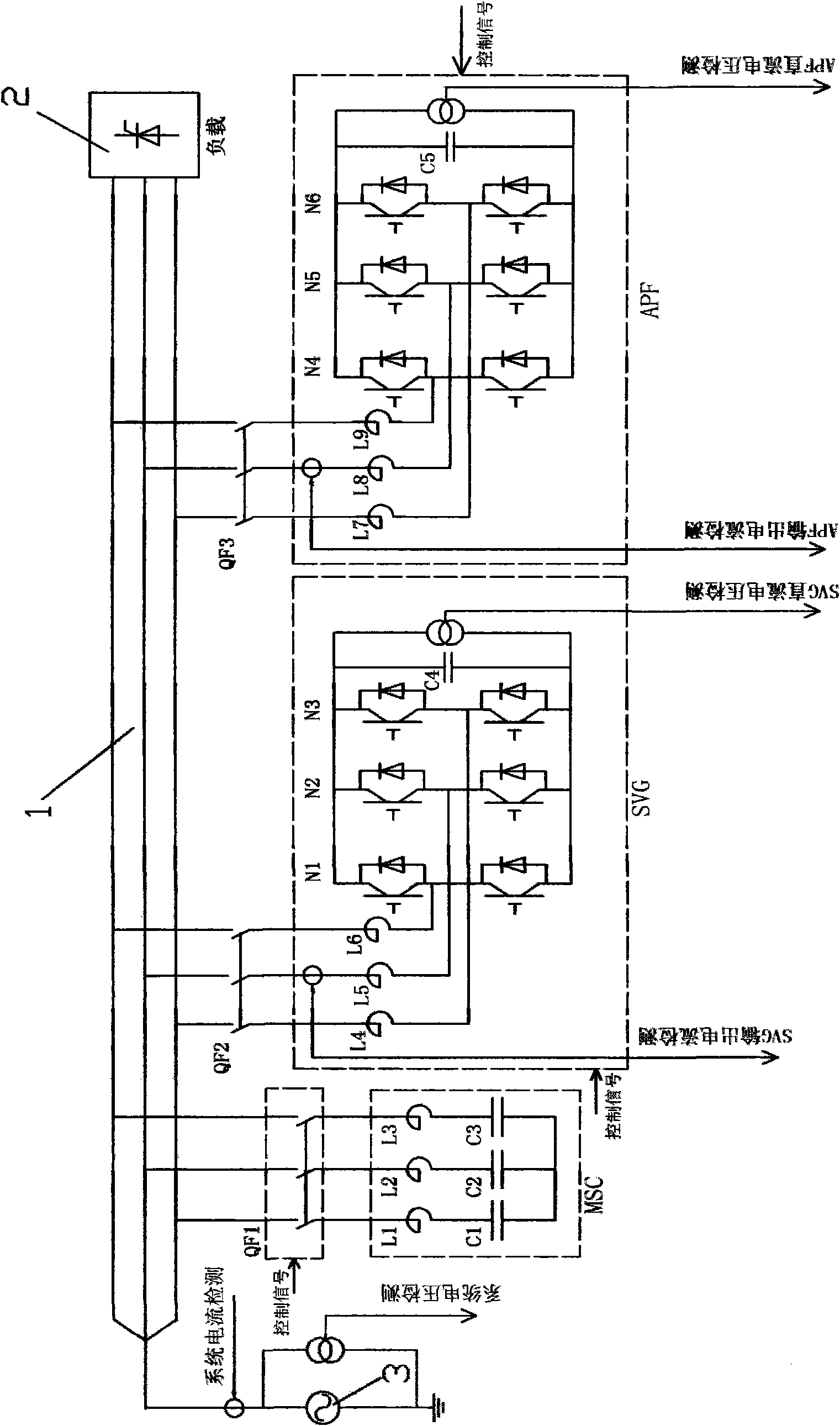
[0017] see figure 1 , the system consists of SVG, MSC and APF connected to grid 1. The following still uses a 2M system as an example to illustrate that the maximum reactive capacity required to be compensated by the power grid is 2M, so the reactive capacity of MSC and SVG in the system needs to be designed to be 1M each, and the 1M capacitive reactive capacity of MSC is used for fixed investment. Switch, the output reactive capacitive capacity is 0 or 1M, SVG can output capacitive reactive capacity 1M to inductive capacity 1M by adjusting, so the reactive power compensation capacity output by the system can be continuous between inductive 1M and capacitive 2M The change meets the capacitive reactive power compensation of the power grid 2M, and at the same time, it can also meet the inductive reactive power compensation of the power grid 1M. Generally speaking, the amount of inductive compensation required by the grid is smaller than the amount of capacitive compensation, s...


PUM


Abstract

The invention relates to a harmonic-var comprehensive compensation system based on two-way dynamic reactive power compensation devices. The system consists of a mechanically switched capacitor MSC, a static var generator SVG and an active power filter APF which are connected with a power network 1. The system uses the SVG to replace a thyristor controlled reactor TCR in the prior harmonic-var comprehensive compensation system, and as the SVG generates reactive power through electric-energy transformation to perform var compensation, the SVG does not need large-capacity reactors, capacitors and other energy storage elements. Therefore, the capacity of the MSC and the SVG is reduced by half at least; system volume is effectively reduced; and system cost is lowered. Meanwhile, as the SVG uses a full-controlled switching device IGBT, the SVG is fast in response and has the system response time which is less than 20 ms and much superior to that of the TCR. In addition, as the SVG does not produce harmonic current, the capacity of the APF is reduced, thus the volume and cost of the system are further reduced.

Description

technical field [0001] The invention relates to a dynamic reactive power compensation device for a power grid, in particular, it is a harmonic and reactive power comprehensive compensation system based on a bidirectional dynamic reactive power compensation device. Background technique [0002] In the existing technology, a kind of harmonic and reactive power dynamic comprehensive compensation system based on thyristor-controlled reactor type reactive power compensation device (referred to as SVC) publicly used in China is as follows: Figure 4 As shown, it is composed of a thyristor phase-controlled reactor (abbreviated as TCR), an active power filter (abbreviated as APF), and a mechanically switched capacitor (abbreviated as MSC) connected to the grid 1. In this system, the reactive power compensation capacity of MSC and TCR should be the same as the maximum reactive power capacity required to be compensated by the grid. Let’s take a system with a capacity of 2M as an examp...

Claims


Application Information

Patent Timeline
Patent Type & Authority Applications(China)
IPC IPC(8): H02J3/18H02J3/01
CPCY02E40/40Y02E40/22Y02E40/12Y02E40/10Y02E40/20
Inventor 许强张建荣王启华高鹏
Owner 西安赛博电气有限责任公司
Why Eureka
Try Eureka