Adjustment device and adjustment method for output enable signal

A technology for adjusting devices and signals, applied in the field of adjustment technology for output enabling signals, to avoid rewriting problems

Inactive Publication Date: 2012-12-19
HUAYING OPTOELECTRONICS +1
View PDF5 Cites 0 Cited by
  • Summary
  • Abstract
  • Description
  • Claims
  • Application Information

AI Technical Summary

Problems solved by technology

But in fact, the voltage waveforms of the signal G1_output and the signal G2_output will not be a perfect square wave, and there will be a delay from the high potential to the low potential and from the low potential to the high potential, such as figure 1 shown by the solid line

Method used


Image

  • Adjustment device and adjustment method for output enable signal
  • Adjustment device and adjustment method for output enable signal
  • Adjustment device and adjustment method for output enable signal

Examples


Embodiment Construction

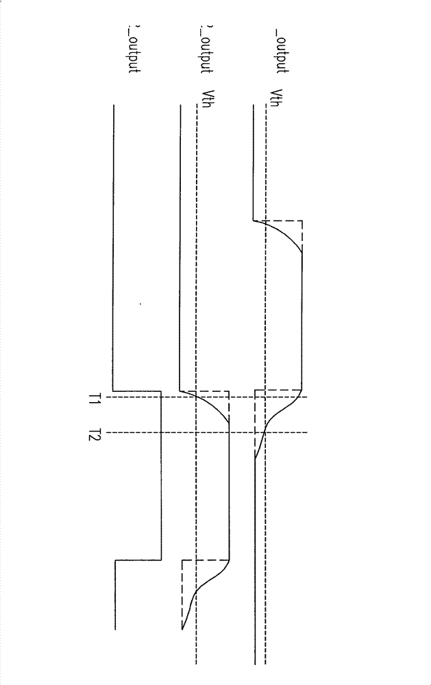
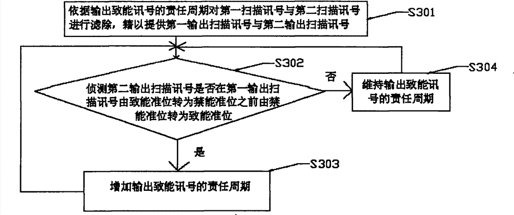
[0047] Conventional liquid crystal displays have rewriting problems. In view of this, the embodiments of the present invention can filter the first scan signal and the second scan signal according to the duty cycle of the output enable signal, so as to provide the first output scan signal and the second output scan signal. Therefore, the overlapping of the first output scan signal and the second output scan signal can be effectively avoided.

[0048] In addition, it is worth mentioning that, for different liquid crystal displays, the optimal value of the duty cycle for outputting the enable signal is not necessarily the same. Therefore, in the embodiment of the present invention, it can be detected whether the second output scan signal changes from the disable level to the enable level before the first output scan signal changes from the enable level to the disable level. If the second output scan signal changes from the disable level to the enable level before the first outp...


PUM


Abstract

The invention relates to an adjustment device and an adjustment method for an output enable signal. The adjustment method comprises the following steps: according to the duty cycle of the output enable signal, filtering a first scanning signal and a second scanning signal to provide a first output scanning signal and a second output scanning signal; and if the second output scanning signal is converted into an enable quasi-phase from a disable quasi-phase before the first output scanning signal is converted into the disable quasi-phase from the enable quasi-phase, increasing the duty cycle ofthe output enable signal. Therefore, the re-write problem is prevented.

Description

technical field [0001] The present invention relates to an adjustment technology for an output enable signal, and in particular relates to an adjustment technology for an output enable signal suitable for a gate driver. Background technique [0002] In recent years, liquid crystal displays have become the mainstream of display products on the market due to their advantages such as low-voltage operation and no radiation. Generally speaking, a liquid crystal display mainly includes a gate driver, a source driver and a panel. It is worth mentioning that there is a problem of rewriting when the conventional liquid crystal display is driven, and the details are as follows. [0003] figure 1 is a schematic diagram of a well-known rewriting phenomenon. Please refer to figure 1 , the signal G1_output is an output scan signal provided by the gate driver to the first scan line, wherein the first scan line is coupled to the first row of pixel transistors. The signal G2_output is a...

Claims


Application Information

Patent Timeline
Patent Type & Authority Patents(China)
IPC IPC(8): G09G3/36
Inventor 林书扬刘佑安
Owner HUAYING OPTOELECTRONICS
Why Eureka
Try Eureka