Minitype electromagnetic valve

A solenoid valve, small technology, applied in circuits, valve details, valve devices, etc., can solve the problems of coil heating and coil resistance increase, and achieve the effect of suppressing heat generation, reducing resistance value, and improving insulation

Inactive Publication Date: 2011-01-05
CKD
View PDF7 Cites 1 Cited by
  • Summary
  • Abstract
  • Description
  • Claims
  • Application Information

AI Technical Summary

Problems solved by technology

[0002] In a small solenoid valve, although it is necessary to increase the electric power to secure the required attractive force, if the duty cycle of the coil occupying the space between the fixed iron core and the valve cover is low, the resistance of the coil increases, and the heat generated by the coil becomes question

Method used


Image

  • Minitype electromagnetic valve
  • Minitype electromagnetic valve
  • Minitype electromagnetic valve

Examples


no. 1 approach

[0063] Composition of Small Solenoid Valve

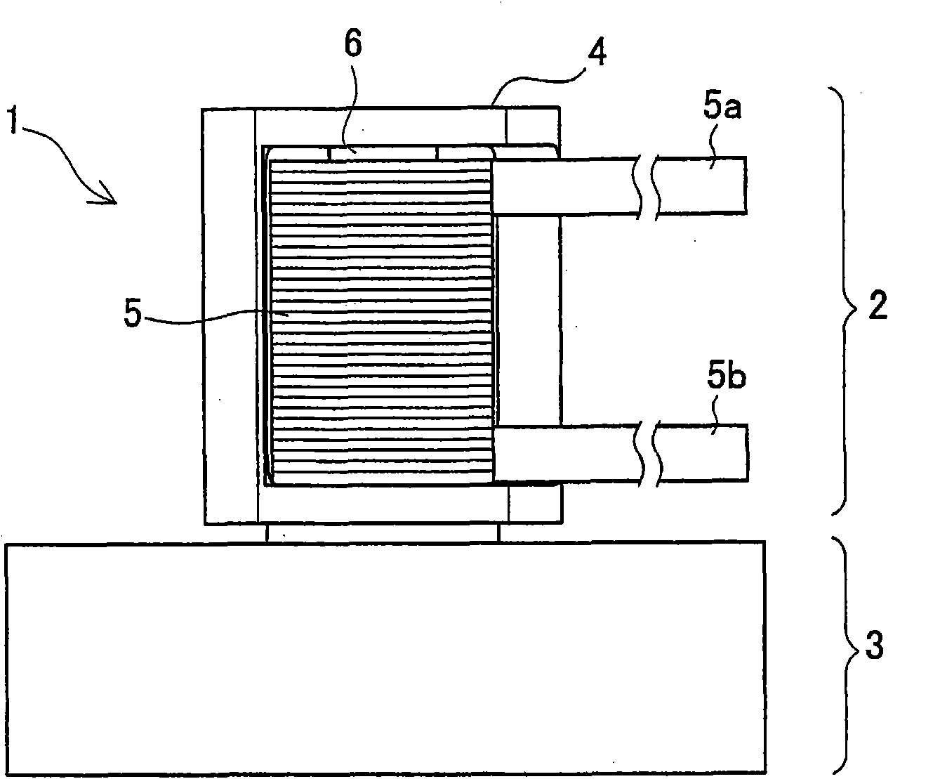
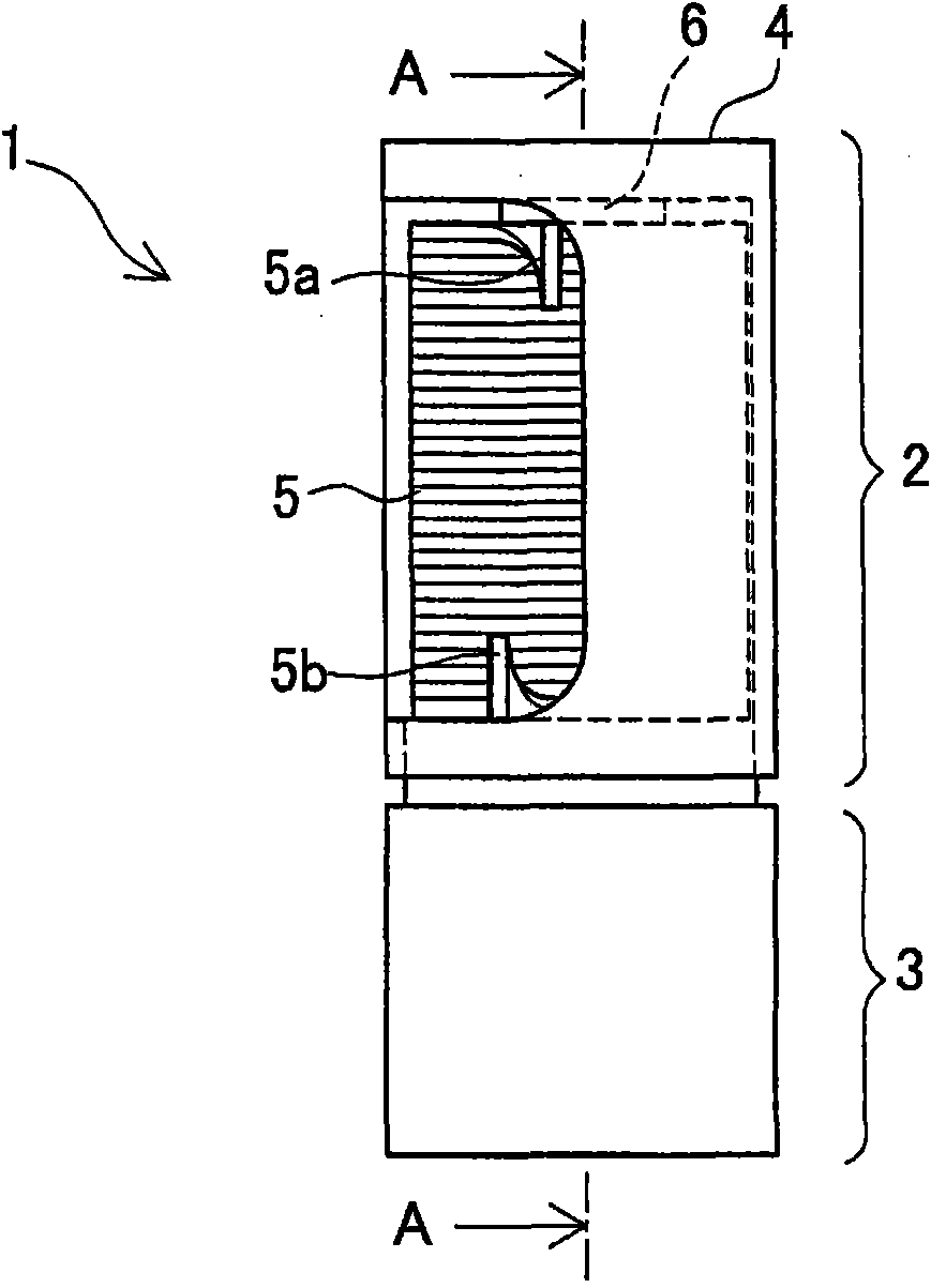
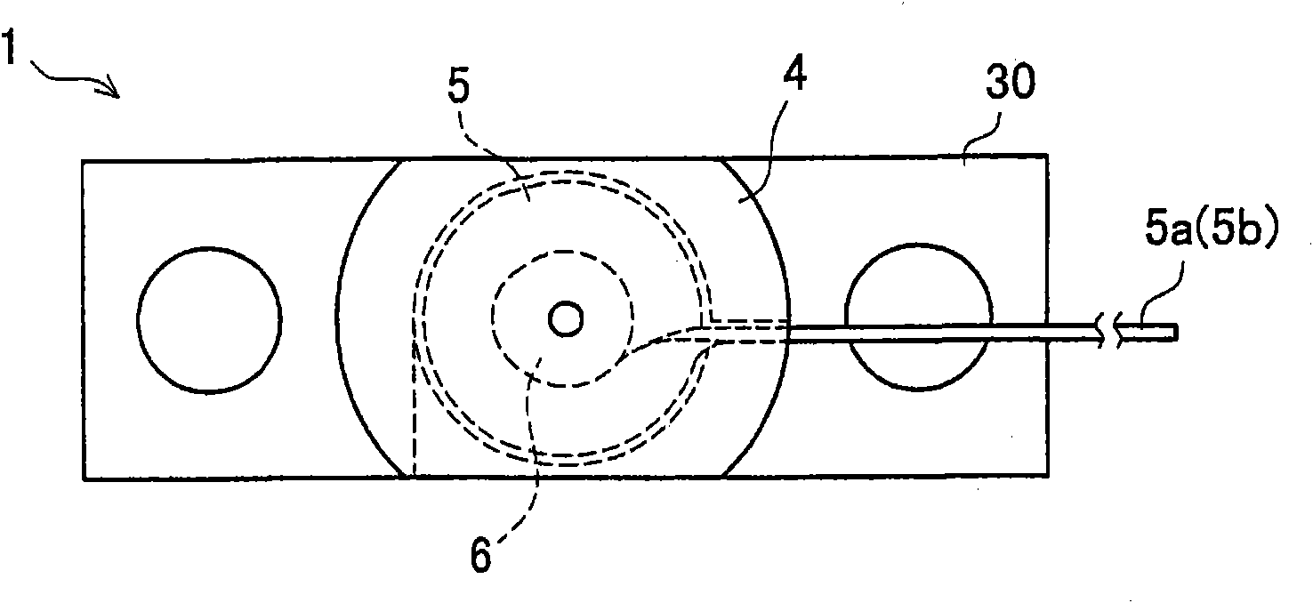
[0064] figure 1 A front view of the small solenoid valve 1 is shown. figure 2 Indicates the right view. image 3 Indicates a top view. Figure 4 Indicates the upper perspective view of the appearance. Figure 5 An exploded perspective view of the small solenoid valve 1 is shown. Figure 15 express figure 2 Cutaway view of AA.

[0065] Such as figure 1 As shown, the small solenoid valve 1 is composed of a solenoid part 2 and a main body part 3 .

[0066] Such as Figure 15 As shown, a first flow path 31 and a second flow path 32 are formed inside the valve body 30 of the main body portion 3 , and the first flow path 31 and the second flow path 32 communicate with the valve chamber 33 . A valve hole 35 is formed in a communication portion where the second flow path 32 communicates with the valve chamber 33 , and a valve seat 34 is formed in a peripheral portion of the valve hole 35 .

[0067] Solenoid section 2 as Figu...

no. 2 approach

[0108] Compared with the small solenoid valve 1 of the first embodiment, the small electromagnetic integrated valve 80 of the second embodiment has a width of the valve body 30 of 11 mm and a width of the solenoid part 2 of 10 mm. There is no difference, therefore, the small solenoid valve 1 will not be described.

[0109] Figure 17 A perspective view showing the appearance of the small solenoid integrated valve 80 . Figure 18 It shows a side view of the small solenoid integrated valve 80 .

[0110] Such as Figure 17 and Figure 18 As shown, in the small solenoid integrated valve 80 , the small solenoid valves 1A, 1B, 1C, and 1D are arranged facing the same direction. In the small solenoid valves 1A, 1B, 1C, and 1D, the width of the valve main body is larger than the width of the solenoid portion, so the solenoid portions do not contact each other.

[0111] The small solenoid valves 1A, 1B, 1C, and 1D face the same direction, so the coil insertion hole 40B of the small...


PUM


Abstract

The present invention provides a minitype electromagnetic valve, having a solenoid part (2) and a main body part (3). The solenoid part (2) includes a coil (5), a fixed core (6) fixed on a hollow part of the coil (5), a movable core (7) attracted by the fixed core (6), a valve core (9) fixed on the movable core (7), and a hollow outer housing (4); the main body part (3) includes a valve chamber (33) where the valve core (9) is embedded, a flow-in path (31) and a flow-out path (32) communicated with the valve chamber (33), a valve main body (30) equipped with the flow-in path (31) and the flow-out path (32), a valve seat (34) arranged in the valve main body (30) and contacted with / separating from the valve core (9), and a leaf spring (8) for conjoining the valve core (9) and the valve seat (34), wherein the coil is an flat coil (5), and a coil insertion hole (40) of the flat coil (5) is formed on one side face of the outer housing (4) so as to prevent the coil from heating and improve assembly performance.

Description

technical field [0001] The present invention relates to a small solenoid valve using a coil. Background technique [0002] In a small solenoid valve, although it is necessary to increase the electric power to secure the required attractive force, if the duty cycle of the coil occupying the space between the fixed iron core and the valve cover is low, the resistance of the coil increases, and the heat generated by the coil becomes question. [0003] In the past, as techniques for improving the duty cycle of small solenoid valves, there were, for example, Figure 19 The solenoid valve 100 described in Patent Document 1 is shown. [0004] The solenoid valve 100 has a solenoid part 110 in which a coil 113 having a square cross section is wound around a bobbin 115 formed in a hollow cylindrical shape. [0005] By making the coil 113 have a square cross section, it is possible to reduce the gap between the stacked coils 113 and eliminate unnecessary space. [0006] Patent Docum...

Claims


Application Information

Patent Timeline
IPC IPC(8): F16K31/06F16K49/00H01F5/00
Inventor 西村康典西田成伸井上贵史
Owner CKD
Why Eureka
Try Eureka