RC triggered ESD protection circuit for integrated circuit

An ESD protection, integrated circuit technology, applied in the electronic field, can solve the problems of large resistance and capacitance, RC trigger ESD protection circuit occupying a large chip area and so on

Inactive Publication Date: 2014-07-09
UNIV OF ELECTRONICS SCI & TECH OF CHINA
View PDF4 Cites 19 Cited by
  • Summary
  • Abstract
  • Description
  • Claims
  • Application Information

AI Technical Summary

Problems solved by technology

[0007] The present invention aims at the technical problem that the RC time constant of the RC trigger circuit in the conventional RC trigger ESD protection circuit used for integrated circuits is relatively large, requiring relatively large resistance and capacitance, thus causing the RC trigger ESD protection circuit to occupy too large a chip area. , providing an RC trigger ESD protection circuit for integrated circuits

Method used


Image

  • RC triggered ESD protection circuit for integrated circuit
  • RC triggered ESD protection circuit for integrated circuit
  • RC triggered ESD protection circuit for integrated circuit

Examples


Embodiment 1

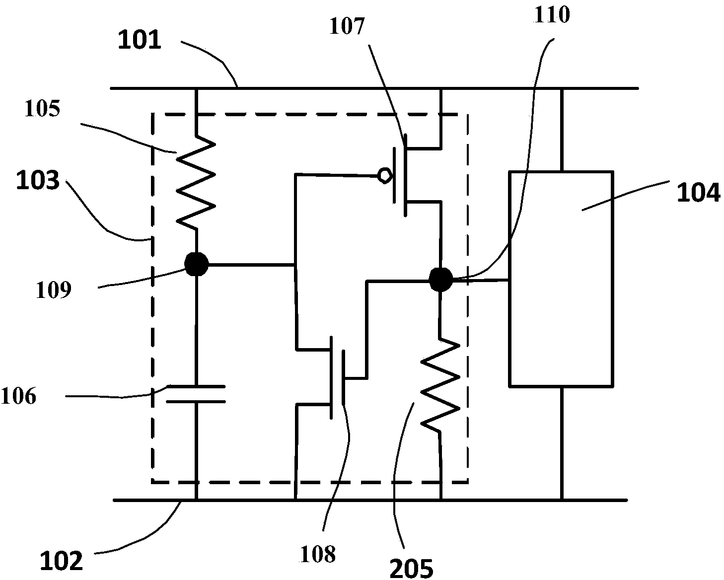
[0020] An RC trigger ESD protection circuit for integrated circuits such as figure 2 As shown, it includes: RC trigger circuit 103 and ESD clamping device 104 . The trigger circuit 103 includes two resistors 105 and 205 , a capacitor 106 , a PMOS transistor 107 and an NMOS transistor 108 . After the first resistor 105 and capacitor 106 are connected in series, the resistor is connected to the VDD power supply line 101, and the capacitor is connected to the VSS power supply line 102; the connection point 109 between the first resistor 105 and the capacitor 106 is connected to the gate of the PMOS transistor 107 and the gate of the NMOS transistor 108. Drain, the source of the PMOS transistor 107 is connected to the VDD power supply line 101, the source of the NMOS transistor 108 is connected to the VSS power supply line 102, and the drain of the PMOS transistor 107 and the gate of the NMOS transistor 108 are connected to each other at the connection point 110 connected to the ...

Embodiment 2

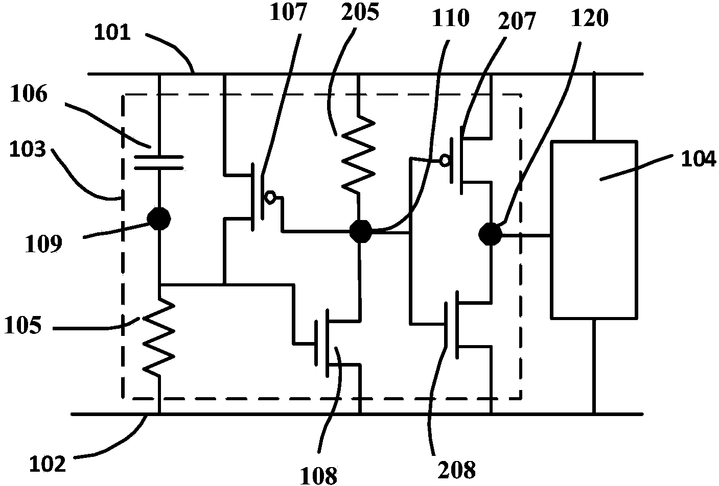
[0025] Another RC trigger type ESD protection circuit for integrated circuits provided by the present invention, such as image 3 As shown, it includes: RC trigger circuit 103 and ESD clamping device 104 . The trigger circuit 103 includes two resistors 105 and 205 , a capacitor 106 , two PMOS transistors 107 and 207 , and two NMOS transistors 108 and 208 . The capacitor after the first resistor 105 and capacitor 106 are connected in series is connected to the VDD power supply line 101, and its resistor is connected to the VSS power supply line 102; the connection point 109 between the first resistor 105 and the capacitor 106 is connected to the drain of the first PMOS transistor 107 and the first The gate of the NMOS transistor 108, the source of the first PMOS transistor 107 is connected to the VDD power supply line 101, the source of the first NMOS transistor 108 is connected to the VSS power supply line 102, the gate of the first PMOS transistor 107 and the first NMOS trans...


PUM


Abstract

The invention provides an RC triggered ESD protection circuit for an integrated circuit, and belongs to the technical field of electronics. According to the RC triggered ESD protection circuit, an RC series circuit composed of a capacitor and a resistor triggers and starts a PMOS tube, the electric potential of an electric potential point (109) is increased by currents, therefore, an NMOS tube is started, and the electric potential of the electric potential point (109) is reduced; finally, positive feedback is formed so as to guarantee that output of a triggering circuit (103) is at a high electric potential. The RC triggered ESD protection circuit only needs 5-15-ns RC triggering time; compared with 20-ns RC triggering time of a traditional triggering circuit, the capacitance value and the resistance value are reduced to about one tenth of the original capacitance value and the original resistance value, namely, the layout area of the triggering circuit is also reduced to about one tenth of the original layout area. In addition, output voltage of an electric potential point (110) can be adjusted by adjusting the width-to-length ratio of the PMOS tube (107) and the magnitude of a second resistor (205), and therefore the discharge capacity of ESD currents of an ESD clamping device (104) is adjusted.

Description

technical field [0001] The invention belongs to the field of electronic technology, and relates to an electrostatic discharge (ElectroStatic Discharge, ESD for short) protection circuit technology for semiconductor integrated circuit chips, in particular to an RC trigger type ESD protection circuit for integrated circuits. Background technique [0002] In the process of integrated circuit production, packaging, testing, storage, and handling, electrostatic discharge, as an inevitable natural phenomenon, is ubiquitous. With the reduction of the feature size of integrated circuit technology and the development of various advanced technologies, it is more and more common for integrated circuits to be damaged by ESD phenomena. Relevant research and surveys have shown that 30% of integrated circuit failure products are due to electrostatic discharge. caused by. Therefore, it is very important to use high-performance ESD protection devices to protect integrated circuit circuits. ...

Claims


Application Information

Patent Timeline
Patent Type & Authority Applications(China)
IPC IPC(8): H02H9/02H01L27/02
Inventor 乔明马金荣齐钊石先龙曲黎明张波
Owner UNIV OF ELECTRONICS SCI & TECH OF CHINA
Why Eureka
Try Eureka