Semiconductor device and method for manufacturing the same

a technology of semiconductor devices and semiconductors, applied in semiconductor devices, electrical devices, nanotechnology, etc., can solve the problems of limiting the freedom of device design, increasing parasitic capacitance, and one skilled person in the art being unable to reduce both parasitic resistance and parasitic capacitance together, so as to reduce parasitic resistance and reduce parasitic capacitance , the effect of reducing parasitic resistan

Active Publication Date: 2011-08-11
INST OF MICROELECTRONICS CHINESE ACAD OF SCI
View PDF9 Cites 136 Cited by
  • Summary
  • Abstract
  • Description
  • Claims
  • Application Information

AI Technical Summary

Benefits of technology

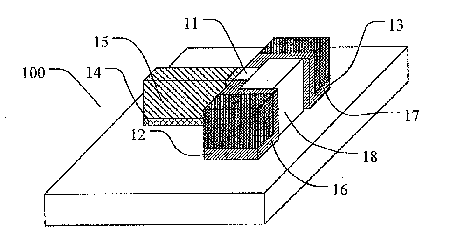
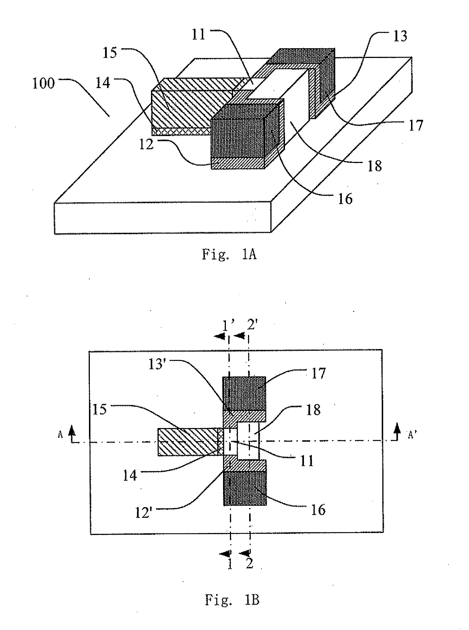
[0016]Since in the inventive semiconductor device the gate does not extend between the source/drain regions parallel to the source/drain regions, there is no capacitive coupling between the source/drain regions and the gate. Thus, the inventive semiconductor device has a reduced parasitic capacitance. Meanwhile, the inventive semiconductor device allows a reduced parasitic resistance by providing source/drain regions having a relatively larger thickness.
[0017]The inventive semiconductive device also allows further suppression of the parasitic effect relevant with the parasitic capacitance and the parasitic resistance by providing extensions adjacent to the channel region in the fin so as to decreas...

Problems solved by technology

Moreover, the capacitive coupling between the source/drain regions and the gate limits the freedom of device design.
However, the source/drain regions having a larger thickness also means an increased coupling area between the source/drain regions and the gate, which in turn causes a parasitic capacita...

Method used


Image

  • Semiconductor device and method for manufacturing the same
  • Semiconductor device and method for manufacturing the same
  • Semiconductor device and method for manufacturing the same

Examples


Embodiment Construction

[0025]Reference will now be made in detail to the preferred embodiments of the present invention, examples of which are illustrated in the accompanying drawings, wherein like reference numerals refer to same elements throughout. The figures are not drawn to scale, for the sake of clarity.

[0026]It should be understood that when one layer or region is referred to as being “above” or “on” another layer or region in the description of device structure, it can be directly above or on the other layer or region, or other layers or regions may be is intervened therebetween. Moreover, if the device in the figures is turned over, the layer or region will be “under” or “below” the other layer or region.

[0027]In contrast, when one layer is referred to as being “directly on” or “on and adjacent to” another layer or region, there are not intervening layers or regions present.

[0028]Some particular details of the invention will be described, such as an exemplary structure, material, dimension, proc...


PUM


Abstract

The present application discloses a semiconductor device formed on a SOI substrate which comprises a buried insulating layer and a semiconductor layer on the buried insulating layer and a method for manufacturing the same, wherein a fin of semiconductive material having two opposing sides perpendicular to a main surface of the SOI substrate is provided in the semiconductor layer, said semiconductor device comprising: a source region and a drain region provided at two ends of the fin respectively; a channel region provided at a central portion of the fin; and a stack of gate dielectric and gate conductor provided at one side of the fin, where the gate conductor is isolated from the channel region by the gate dielectric, wherein the gate conductor extends away from the one side of the fin in a direction parallel to the main surface of the SOI substrate. The semiconductor device has an improved short channel effect and a reduced parasitic capacitance and resistance, which contributes to an improved electrical property and facilitates scaling down of the transistor.

Description

[0001]This application is based on, and claims priority from Chinese Patent Application Serial No. 200910235339.9, filed on Sep. 30, 2009, entitled “Semiconductor Device and Method for Manufacturing the Same”, the contents of which are incorporated herein by reference in their entirety.BACKGROUND OF THE INVENTION[0002]1. Field of Invention[0003]The present invention relates to a semiconductor device and a method for manufacturing the same, in particular, to an improved FinFET formed on a semiconductor-on-insulator (SOI) substrate.[0004]2. Description of Prior Art[0005]One important trend in the integrated circuits is scaling down of metal-oxide-semiconductor field effect transistors (MOSFETs) so as to achieve a high integration degree of devices and reduce a cost of manufacture. However, it is well known that short channel effect occurs with a reduced size of the MOSFET, due to which, when the size of the MOSFET is reduced, the gate of the MOSFET has a smaller effective length and a...

Claims


Application Information

Patent Timeline
IPC IPC(8): H01L29/78H01L21/84B82Y99/00
CPCH01L29/66795H01L29/66742H01L29/785
Inventor ZHU, HUILONG
Owner INST OF MICROELECTRONICS CHINESE ACAD OF SCI
Why Eureka
Try Eureka