[0015]Use of perpendicularly aligned CNTs as
electrode materials can significantly improve
capacitor performance. Perpendicularly aligned CNTs can provide an enhanced specific surface area, improved charge transport capability, and excellent
electrolyte accessibility, making them ideal
electrode materials for high performance ultracapacitors.
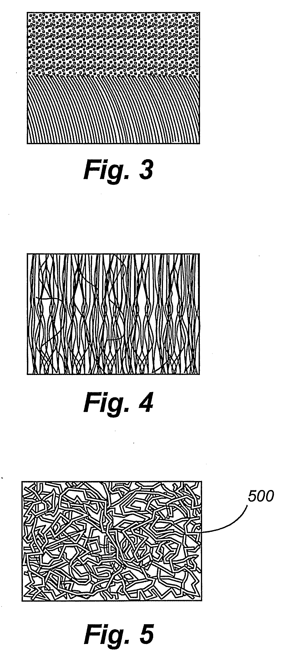
[0016]Compared to randomly entangled CNTs, aligned CNTs can be better synthesized for ultracapacitor applications. Randomly entangled CNT-based electrodes are commonly prepared by blending the CNTs with an insulting
polymer binder (at 5˜10 wt %), e.g., poly(vinylidene
fluoride), polytetrafluoroethylenel, or poly(vinylidene
chloride). The use of an insulating
polymer can lower electrical
conductivity of the resulting electrodes, leading to low performance for the capacitors. In contrast, aligned CNTs can be grown as a film perpendicularly on a substrate, including
metal substrates, without a
polymer binder being required, thereby ensuring high electrical
conductivity for the
electrode. The aligned CNT structure should provide improved charge transport properties, as each of the constituent aligned CNTs can be connected directly onto a common electrode to maximize the charge mobility, i.e., participation of each individual tube in the charge /
discharge of the
capacitor. This indicates a combined charge capacity from all individual tubes of the aligned CNT electrode, and thus enhanced
energy density for the
capacitor. In turn, the
stored energy can be delivered rapidly through each individual tube of the electrode, thereby providing excellent
power density for the capacitor.
[0017]Compared to randomly entangled CNTs, aligned CNTs can have better defined pore structures and higher specific surface areas. The surface area of randomly entangled CNTs is determined by the open space between entangled fibrils. Similarly, the surface area of aligned CNTs is determined by the open space between highly aligned tubes. The inter-CNT open space is in the range of tens of nanometers, indicating high mesoporosity and
electrolyte accessibility. The aligned structure can provide a well-defined surface area for each of the constituent CNTs to be accessible to the electrolyte molecules, resulting in higher surface area for aligned CNTs. Moreover, under appropriate
plasma conditions, the top end-caps of aligned CNTs can be properly opened without any
observable structural change for the sidewalls. Once opened, the aligned structure allows access to the inner cavity of each of the constituent aligned CNTs collectively through a conducting substrate, thereby introducing additional mesoporosity to the electrode. The diameters of the opened tubes (up to tens of nanometers) are commonly larger than the sizes (ionic diameters) of the charged electrolyte ions. The well-defined alignment, in connection with the tip-opened structure, can impart to the aligned CNTs a higher specific surface area than that of randomly entangled CNTs. Higher specific surface area in turn translates into enhanced
energy density for ultracapacitors.
[0018]Mesoporosity can be important to realizing
high capacitance for the electrode and high performance for the ultracapacitor. As will be appreciated, the
capacitance of conventional carbon-based electrodes decreases gradually with increasing discharging
current density. This is so because currents, which are too large, may block the entrances of the micropores. Therefore, the energy stored can be withdrawn only at limited
discharge rates and at low frequencies or by
Direct Current (“DC”) techniques. In contrast, due to the high mesoporosity and enhanced electrolyte
accessibility of aligned CNTs, fast
charge injection and withdrawal are feasible for CNTs, meaning
high capacitance at high frequencies. In other words, the overall enhanced mesoporosity (from both internal and external walls of tubes) and electrolyte accessibility of aligned CNTs can result in even higher
capacitance and performance than capacitors fabricated from randomly entangled CNTs.
[0034]The present invention can provide a number of advantages depending on the particular configuration. For example, the combination of an
ionic liquid and a polymer host can provide
environmentally friendly solid-state electrolytes suitable for use in high performance and stable electrochemical devices. Environmentally stable ionic liquids can have attractive properties, including high
ionic conductivity, large
electrochemical window, excellent thermal and
chemical stability, non-volatility, non-flammability, non-
toxicity, and negligible electrolyte depletion and are readily combinable with well-developed Gel
Polymer Electrolyte (GPE) technology to provide an
environmentally friendly,
solid-state,
Ionic Liquid-incorporated, Gel
Polymer Electrolyte (ILGPE). Being
solid-state, ILGPEs can possess distinct advantages over liquid electrolytes, including reduced reactivity, reduced leakage, improved safety, better shape flexibility, better
processing characteristics, and better manufacturing integrity. In a conventional GPE, an
organic solvent is needed as the
plasticizer. In an ILGPE, the
ionic liquid acts as both the salt and the
solvent (
plasticizer) without a conventional
organic solvent. Absence of the environmentally unstable organic solvents in the ILGPE ensures the improved stability of ILGPEs over conventional GPEs. The combination of the unique properties of aligned CNTs (e.g., high electrical
conductivity, high specific surface area, high charge transport capability, and high electrolyte accessibility) as electrodes with the unique properties of
environmentally friendly ionic liquids (e.g., high
ionic conductivity, large
electrochemical window, excellent
thermal stability, non-volatility, non-flammability, non-
toxicity, and negligible electrolyte depletion) as electrolytes can overcome the limitations of currently available ultracapacitors, achieve high performance and long cycle life, and are capable of delivering high power pulses that can satisfy the requirements for
Hybrid Electric Vehicles (HEVs).

