Heat compensation circuit and method for executing in multi-phase DC/DC converter

A technology of DC converters and converters, which is applied in the direction of output power conversion devices, conversion equipment without intermediate conversion to AC, electrical components, etc., which can solve the problems of reducing system reliability and performance. Increase ripple and other issues

Active Publication Date: 2015-05-06
ANALOG DEVICES INT UNLTD
View PDF7 Cites 0 Cited by
  • Summary
  • Abstract
  • Description
  • Claims
  • Application Information

AI Technical Summary

Problems solved by technology

This difference in operating temperature causes the electrical characteristics of the phases (e.g., on-resistance, inductance, current sense resistance, etc.) of the MOSFET switches to be affected differently, resulting in mismatched current supply and increased ripple under the same duty cycle
This temperature imbalance can also lead to "hot spots" that reduce system reliability and performance

Method used


Image

  • Heat compensation circuit and method for executing in multi-phase DC/DC converter
  • Heat compensation circuit and method for executing in multi-phase DC/DC converter
  • Heat compensation circuit and method for executing in multi-phase DC/DC converter

Examples


Embodiment Construction

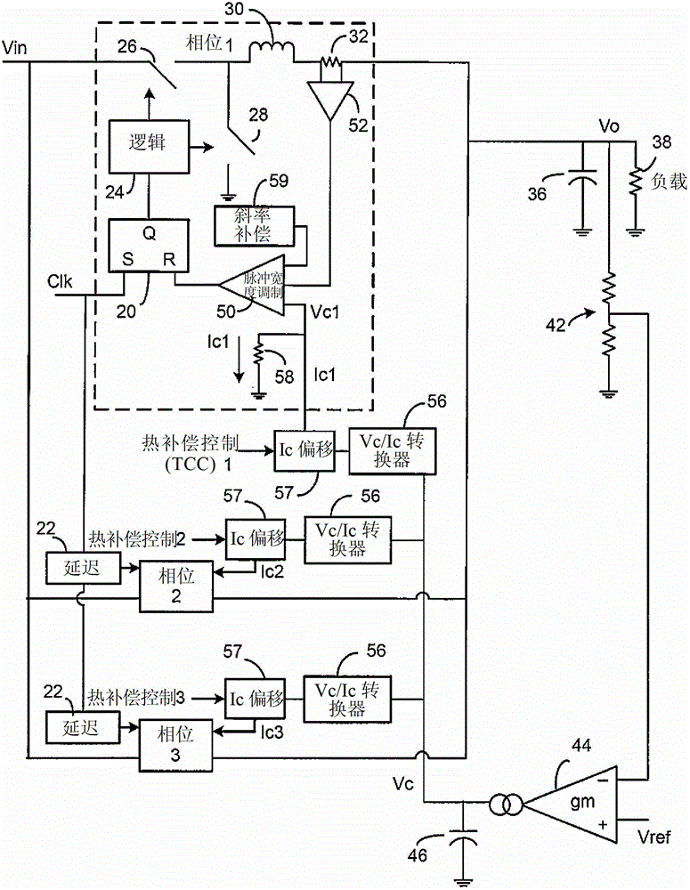
[0016] figure 1 One type of multiphase DC / DC converter using thermal compensation according to one embodiment of the invention is illustrated. Many other types of multiphase converters can also benefit from the invention. The particular type of converter shown is a peak current mode controlled converter.

[0017] figure 1 The operation of the converter section of is conventional and proceeds as follows.

[0018] figure 1 Three phases (Phase 1 to Phase 3) are shown in , but the invention is applicable to any number of phases. For simplicity, only components in Phase 1 are shown. A clock (Clk) signal of each phase is applied to a set input of the RS flip-flop 20 . Each Clk signal is phase-delayed relative to other signals by delay circuit 22 .

[0019] The setting of RS flip-flop 20 produces a high signal at its Q output. In response, logic circuit 24 turns transistor switch 26 on and synchronous rectifier switch 28 off. Both switches can be MOSFETs or other transistors...


PUM


Abstract

A temperature compensation circuit is used in a peak current control multi-phased DC / DC converter, the temperature for each phase in the converter being sensed (72) to generate corresponding first signals (Tcomp) for all the phases. The first signals are averaged to generate a second signal (Tavg) corresponding to the average temperature of all the phases and for each phase, a third signal (TCC) is generated corresponding to the difference between the first signal and the second signal. The third signal is then used to adjust the duty cycle of each phase to control the temperature of each phase to be substantially equal to the average temperature. In the steady state, the output voltage of the converter is a desired regulated voltage and the temperatures of the phases are balanced.

Description

technical field [0001] The present invention relates to multiphase DC / DC converters, and in particular to the thermal control of each phase of said converter. Background technique [0002] Multiphase DC / DC converters are often used in high current applications, such as for generating load currents of 100A or more. Converters employing multiple phases allow sharing of current generation, reduce ripple, and achieve other well-known benefits. There may be two or more phases. For optimal operation, each phase should be identical, but this is not possible due to practical considerations. [0003] For a multi-phase current mode DC / DC converter, each phase typically includes: a pulse width modulation (PWM) comparator; an RS flip-flop, which is used to switch the transistor on and off at a certain duty cycle for regulation ; inductors; current sensing devices (such as low value resistors). The on-time of each phase is controlled by a phase-controlled clock. When a switch is on,...

Claims


Application Information

Patent Timeline
Patent Type & Authority Patents(China)
IPC IPC(8): H02M3/04
CPCH02M3/1584H02M1/0003H02M1/327
Inventor 亦定·谷
Owner ANALOG DEVICES INT UNLTD
Why Eureka
Try Eureka