Liquid cooling system for device

A liquid cooling and equipment technology, applied in mechanical equipment, engine components, engine lubrication, etc., can solve the need for long-term work that cannot be fundamentally solved, the power consumption of compressors and cooling fans is large, and the cost of equipment renewal is high. and other problems, to achieve the effect of avoiding the mismatch of circulation volume, avoiding the hazards of occupational diseases, and occupying a small area

Inactive Publication Date: 2009-12-16
KUNSHAN DINGXIN ELECTRONICS
View PDF0 Cites 10 Cited by
  • Summary
  • Abstract
  • Description
  • Claims
  • Application Information

AI Technical Summary

Problems solved by technology

And because the fan of the radiator is easy to raise dust, the dust in the air is full of dust, for the equipment and staff, the working environment is poor
[0004] For air conditioners that have been used for a long time in the workshop, it is obviously difficult to meet the temperature requirements of the on-site working environment. Therefore, to solve the above problems, it is necessary to increase the cooling and air exchange capacity of the air conditioner. Address long-term work needs
Moreover, the compressor and cooling fan of the cooling system consume a lot of power and occupy a large area

Method used


Image

  • Liquid cooling system for device
  • Liquid cooling system for device

Examples


Embodiment Construction

[0021] Preferred embodiments of the present invention will be described in detail below in conjunction with accompanying drawing:

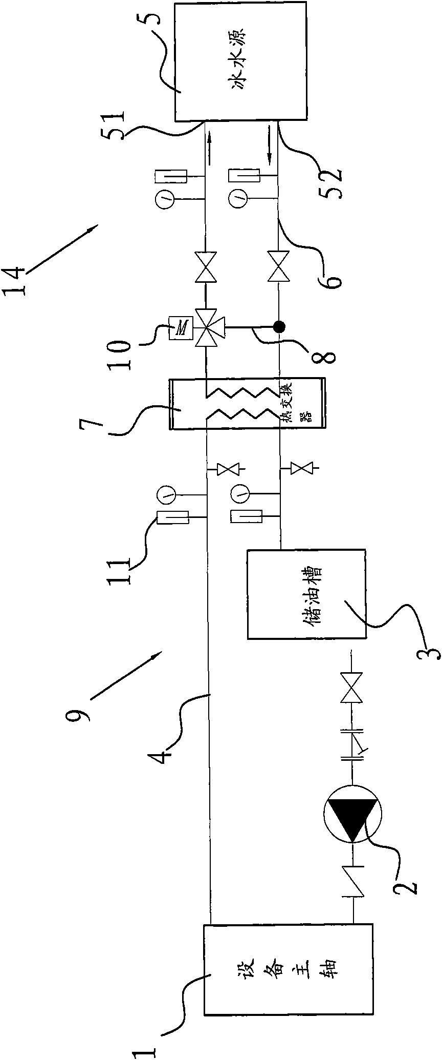
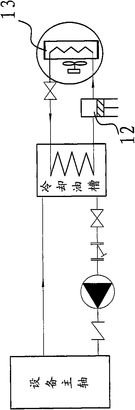
[0022] as attached figure 1 And attached figure 2 Shown in, a kind of equipment liquid cooling system, it comprises heat exchanger 7 and two circulation loops: oil circulation loop 9 and ice water circulation loop 14;

[0023] The oil circulation circuit 9 includes an oil storage tank 3, a circulation pump 2, an equipment main shaft 1, and a heat exchanger 7, and the oil storage tank 3, circulation pump 2, equipment main shaft 1, and heat exchanger 7 are sequentially connected through a circulation oil pipe 4 to form a closed circuit ;

[0024] The ice water circulation circuit 14 comprises an ice water source 5, a heat exchanger 7, and the ice water source 5 is provided with a water inlet 51 and a water outlet 52, and the water outlet 52 of the ice water source 5, the heat exchanger 7, the ice water source The water inlet 51 of 5 is sequentia...


PUM


Abstract

The invention relates to a liquid cooling system for a device, which comprises a heat exchanger and two circulation loops including an oil circulation loop and an ice water circulation loop, wherein the oil circulation loop forms a closed loop by connecting an oil storage tank, a circulating pump, a main shaft of the device and the heat exchanger in turn through circulating oil pipes, and the ice water circulation loop forms a closed loop by connecting an ice water source and the heat exchanger in turn through circulating water pipes; and the cooling oil in the oil circulation loop and the ice water in the ice water circulation loop perform heat exchange in the heat exchanger so as to cool the oil temperature on the main shaft of the device. The liquid cooling system uses the circulation of a cooling medium ice water of the heat exchanger to take away the heat of oil cooling engine oil, and compared with the prior art, compressors and heat radiators for discharging the heat in a workshop out of the workshop are not needed. The liquid cooling system not only reduces the temperature of a working condition, but also removes a compressor radiator fan and prevents workers from being harmed by occupational diseases caused by dust and the like, and the working condition is comparatively comfortable.

Description

technical field [0001] The invention relates to a liquid cooling system for equipment, in particular to a liquid cooling system for cooling oil used for cooling equipment. Background technique [0002] At present, mechanical equipment such as drilling machines are usually concentrated in the factory workshop, and usually the drilling machine cools the circulating oil through the oil cooler compressor. Specifically, as attached figure 2 As shown, the cooling oil in the cooling oil tank flows back into the cooling oil tank through the circulating pump and the main shaft of the drilling machine. A cooling coil is arranged in the cooling oil tank. The two ends of the cooling coil pass through the compressor 12, radiator 13, section The flow valve forms a cooling circuit, which transfers the heat of the drilling machine spindle to the environment of the drilling workshop through the radiator, and then takes the heat out of the workshop through the air-conditioning refrigeration ...

Claims


Application Information

Patent Timeline
Patent Type & Authority Applications(China)
IPC IPC(8): F16N39/02
Inventor 周阳许志华
Owner KUNSHAN DINGXIN ELECTRONICS
Why Eureka
Try Eureka