Furrowing type ridger

A ridging machine and ditch-type technology, which is applied in the direction of tillage machines, agricultural machinery and implements, wheels with shovel grips, etc., can solve problems such as single ridging mode, unfavorable planting, and large ridging resistance , to achieve the effect of flexible use, rich ridging modes, and not easy to slip

Inactive Publication Date: 2010-01-06
陈恳
View PDF0 Cites 4 Cited by
  • Summary
  • Abstract
  • Description
  • Claims
  • Application Information

AI Technical Summary

Problems solved by technology

The existing ridging machines mainly have the following deficiencies: 1. All the existing ridging machines have a ridging mode in which the soil is piled up from both sides to the middle to form a ridge shape, and the ridging mode is single; 2. The ridging resistance is large and it is difficult to walk
Some do not have special walking wheels, and at this time, it is very laborious to advance the machine completely by the force of the cutting tool and the thrust of the operator; while some are designed with walking wheels, but the walking wheels are not equipped with power, so it is relatively difficult to walk. It is difficult, and may even slip on the spot, especially when the soil is relatively wet; 3. The soil particles forming the ridge are relatively large, which not only looks rough, but also is not conducive to planting plants

Method used


Image

  • Furrowing type ridger
  • Furrowing type ridger
  • Furrowing type ridger

Examples


Embodiment Construction

[0024] The present invention will be further explained below in conjunction with the drawings.

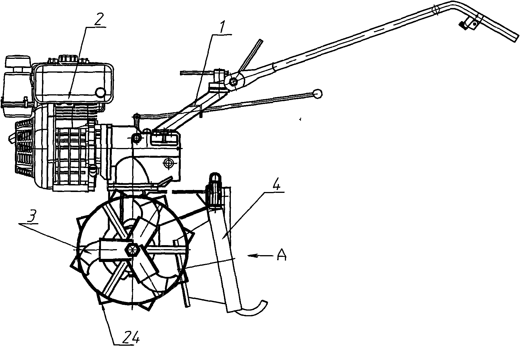
[0025] See figure 1 As can be seen from the figure, the ditch ridger of the present invention is mainly composed of frame 1, power part 2, cutter 3, shaper 4 and operating part. The frame is the installation foundation of the entire ridger. The power part (engine), shaper and operation part are all installed on the basis of the frame.

[0026] The cutter 3 is installed symmetrically on the two ends of the power output shaft 7 for cutting large pieces of soil. The blade 5 on the cutter has a spiral structure. The different spiral directions determine the accumulation of fine soil. see Figure 5 , The blade 5 of the present invention spirals outwards, so the shredded soil is separated and piled up on both sides, forming a ditch in the middle, and naturally forming a ridge between the two ditches. The traditional blade spirals inward, and the soil piles up in the middle to form a ridge. ...


PUM


Abstract

The invention relates to a furrowing type ridger which comprises a frame, a cutting tool and a shaper. A blade on the cutting tool is of an outward helical structure; the shaper is mounted behind the cutting tool on the frame and comprises a furrowing type plate base, a furrowing type plate, a soil breaker, a left clean-up scraper and a right clean-up scraper, wherein the furrowing type plate base is mounted on the central line of the frame; the furrowing type plate is of an inverted trapezoid and is mounted on the furrowing type plate base; the soil breaker is vertically mounted at the front end of the furrowing type plate base; and the left clean-up scraper and the right clean-up scraper are symmetrically mounted at two sides of the furrowing type plate. Road wheels are arranged at two ends of a power output shaft and positioned at the outer side of the cutting tool. The invention has novel ridging mode and stronger adaptability and can carry out ridging and furrowing simultaneously. The road wheels are hard to slide due to being mounted at two ends of the power output shaft and are easier to move. The furrowing type ridger has the advantages that the ridging effect is good, the ridge height is proper, and the cross-section shape and the dimension of the ridge can be designed according to the requirements of users, therefore, the use is flexible.

Description

Technical field [0001] The present invention relates to an agricultural machine, in particular to a ridger. The present invention completes the ridge indirectly by ditching. Background technique [0002] According to the characteristics of sowing and cultivation of different crops, there are different requirements for cultivation and shaping of the land. For example, some crops, such as flue-cured tobacco, peanuts, sweet potatoes, vegetables, sweet potatoes, and corn, are more conducive to the growth of crops and can increase yields when they are grown on ridges. Therefore, ridgers are specially designed in agricultural machinery. [0003] The ridger is developed on the basis of the traditional tiller. The ridger is mainly composed of the frame, the power part, the cutter, the shaping part and the operation part. The frame is the installation foundation of the entire ridger. The power part, The shaping part and the operation part are installed on the basis of the rack. The cutte...

Claims


Application Information

Patent Timeline
Patent Type & Authority Applications(China)
IPC IPC(8): A01B33/16A01B33/10B60B15/02
Inventor 陈恳
Owner 陈恳
Why Eureka
Try Eureka