
Vehicle sunshade device

A sunshade device and vehicle technology, which is applied to vehicle parts, transportation and packaging, windows, etc., can solve the problems of assembly failure and distance smaller than the design value, and achieve the effect of improving assembly operability

Inactive Publication Date: 2012-06-06
TOYOTA BOSHOKU KK
View PDF1 Cites 0 Cited by
  • Summary
  • Abstract
  • Description
  • Claims
  • Application Information

AI Technical Summary

Problems solved by technology

However, there may be cases where the distance between the inner surfaces on the side of the rear pillar is smaller than the design value due to the inclined shape of the rear pillar or the like
The distance between the inner surfaces of such rear pillar sides ( Image 6 The length L1) in the ratio of the distance between the outer surface of the guide rail side ( Image 6 In the case of small length L2), the fixed connection of the left and right guide rails to the winding device will cause mutual interference between the rear column and the guide rails, so that the assembly cannot be carried out

Method used


Image

  • Vehicle sunshade device
  • Vehicle sunshade device
  • Vehicle sunshade device

Examples


Embodiment approach 1

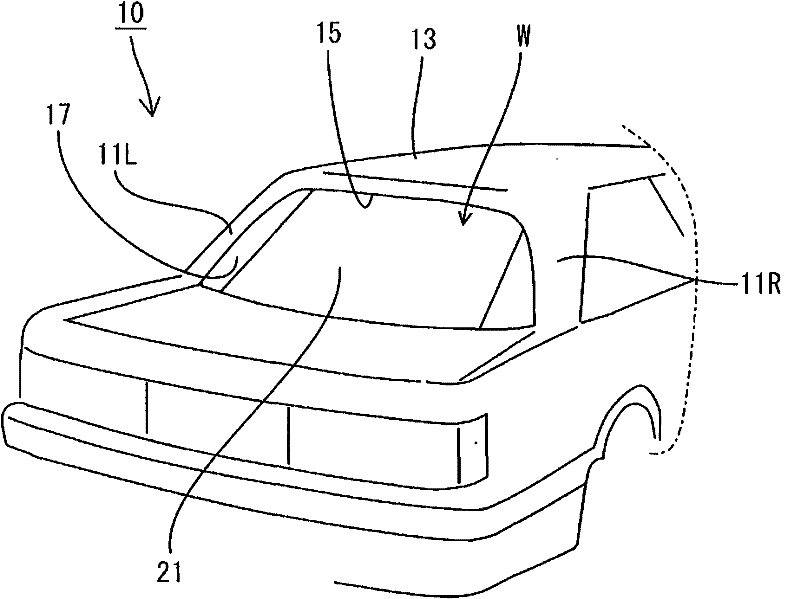
[0024] will now refer to Figure 1 to Figure 8 Embodiment 1 of the present invention will be described. figure 1 It is a perspective view of the vehicle 10 seen from the rear side. figure 1 The 11R and 11L in the middle represent the rear pillars. The rear pillars 11R and 11L together with the roof 13 constitute a window frame 15 into which a rear window glass 17 is installed.

[0025] The vehicle 10 is equipped with the following vehicle sunshade device 20 , and can cover the rear window W (the rear window W is constituted by attaching the rear window glass 17 to the window frame) from the passenger compartment side with the sheet-shaped screen body 21 . This prevents sunlight from entering the cabin through the rear window.

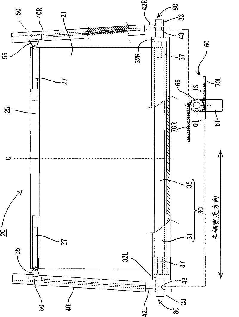
[0026] figure 2 The configuration of the sunshade device 20 for a vehicle is shown, and the sunshade device 20 includes a curtain body 21 , a winding device 30 , a pair of guide rails 40R and 40L, a pair of sliders 50 , a drive unit 60 , and a te...

Embodiment approach 2

[0057] now refer to Figure 9 and Figure 10 , Embodiment 2 of the present invention will be described. The vehicular sunshade device 100 in Embodiment 2 is a modification of the configuration of the vehicular sunshade device 20 in Embodiment 1 in which the slider 150 and the drive unit 160 for reciprocating the slider 150 along the guide rails 40R and 40L are modified. Specifically, the drive unit 160 used in Embodiment 2 includes, for example: a motor 61; an output pulley 66 connected to an unshown motor shaft; inner cables 72a to 72c; and tubular cable guides 71a to 71c, For allowing the respective inner cables 72a to 72c to be loosely inserted in the cable guides 71a to 71c.

[0058] The inner cables 72a to 72c are made of flexible metal wires. The inner cable 72a has connecting portions 73a1 and 73a2 at both ends thereof, one of which is connected to the upper portion of the slider 150 fitted to the right rail 40R. A steering member 110R having a semicircular steering...

Embodiment approach 3

[0069] The sunshade device 200 for a vehicle in the third embodiment is a structure in which the temporary connection portion is modified from the sunshade device 100 for a vehicle in the second embodiment. In short, the temporary connection part 280 in Embodiment 3 is constituted by the second wall parts 205R and 205L having the convex part 220 and the first wall parts 142R and 142L having the convex part groove 143 .

[0070] In the following, reference will be made to Figures 11 to 14 The specific structure of Embodiment 3 of this invention is demonstrated. Since the sunshade device 200 for a vehicle according to Embodiment 3 has a symmetrical shape, Figures 11 to 14 Only the left half of the sunshade device 200 for a vehicle is shown in FIG. In addition, the same reference numerals are attached to the same components in Embodiment 3 as in Embodiments 1 and 2.

[0071] like Figure 11 As shown, the second wall surface portion 205L is provided at the left shaft end of ...


PUM


Abstract

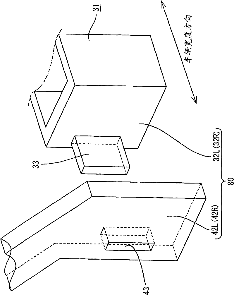
The present invention relates to a vehicle sunshade device 20, which can cover and uncover a rear window provided between a pair of rear pillars 11R and 11L formed in both sides in the vehicle width direction with a screen body 21, and comprising: a winding device 30 for biasing the screen body 21 in its winding-up direction; a pair of guide rails 40R and 40L in both sides in the vehicle width direction of the winding device 30, and capable of being attached to the inner wall of the rear pillar; a pair of sliders 50 fixed at both edges in the vehicle width direction of the screen body 21 respectively, and capable of reciprocately moving within the pair of guide rails 40R and 40L; a drive unit 60 for reciprocately moving the sliders 50 within the guide rails 40R and 40L so as to spread outthe screen body 21 against the biasing force of the winding device 30 and wind up the screen body 21 in a spread-out state with the winding device; a temporary joint part 80 for temporarily connecting the pair of guide rails 40R and 40L with the winding device 30 in a condition, where a relative distance between each of the guide rails 40R and 40L is adjustable, until the present vehicle sunshadedevice 20 is attached to the pair of rear pillars 11R and 11L.

Description

technical field [0001] The invention relates to a sunshade device for vehicles. Background technique [0002] Conventionally, there has been known a sunshade device for a vehicle that unwinds a screen body wound on a winding device along a guide rail by an action of a drive unit, thereby covering a rear window to block sunlight. For example, Japanese Unexamined Patent Publication No. 2007-91224 discloses a sunshade device for a vehicle in which parts such as a guide rail, a reel, and a bearing housing for supporting the reel are connected to each other by a frame tube so as to been integrated. This allows the vehicle assembly line to perform the assembly of the sunshade device for the vehicle to the vehicle in units of units. Therefore, the above-described invention improves the operability compared with the method in which each component of the sunshade device for a vehicle is individually assembled to the vehicle, thereby obtaining a certain effect (improvement in operab...

Claims


Application Information

Patent Timeline
Patent Type & Authority Patents(China)
IPC IPC(8): B60J11/02B60J11/08
CPCB60J1/2044B60J1/2052B60J1/208B60J1/2025
Inventor 竹内功一上角好孝加藤大策
Owner TOYOTA BOSHOKU KK
Learn More