Adaptive non-linearity compensation in coherent receiver

An optical receiver and a technology for receiving signals, applied in the field of optical communication, can solve problems such as reducing overall system performance

Inactive Publication Date: 2010-01-20
ALCATEL LUCENT SAS
View PDF0 Cites 12 Cited by
  • Summary
  • Abstract
  • Description
  • Claims
  • Application Information

AI Technical Summary

Problems solved by technology

This introduces additional nonlinear effects that degrade overall system performance

Method used


Image

  • Adaptive non-linearity compensation in coherent receiver
  • Adaptive non-linearity compensation in coherent receiver
  • Adaptive non-linearity compensation in coherent receiver

Examples


Embodiment Construction

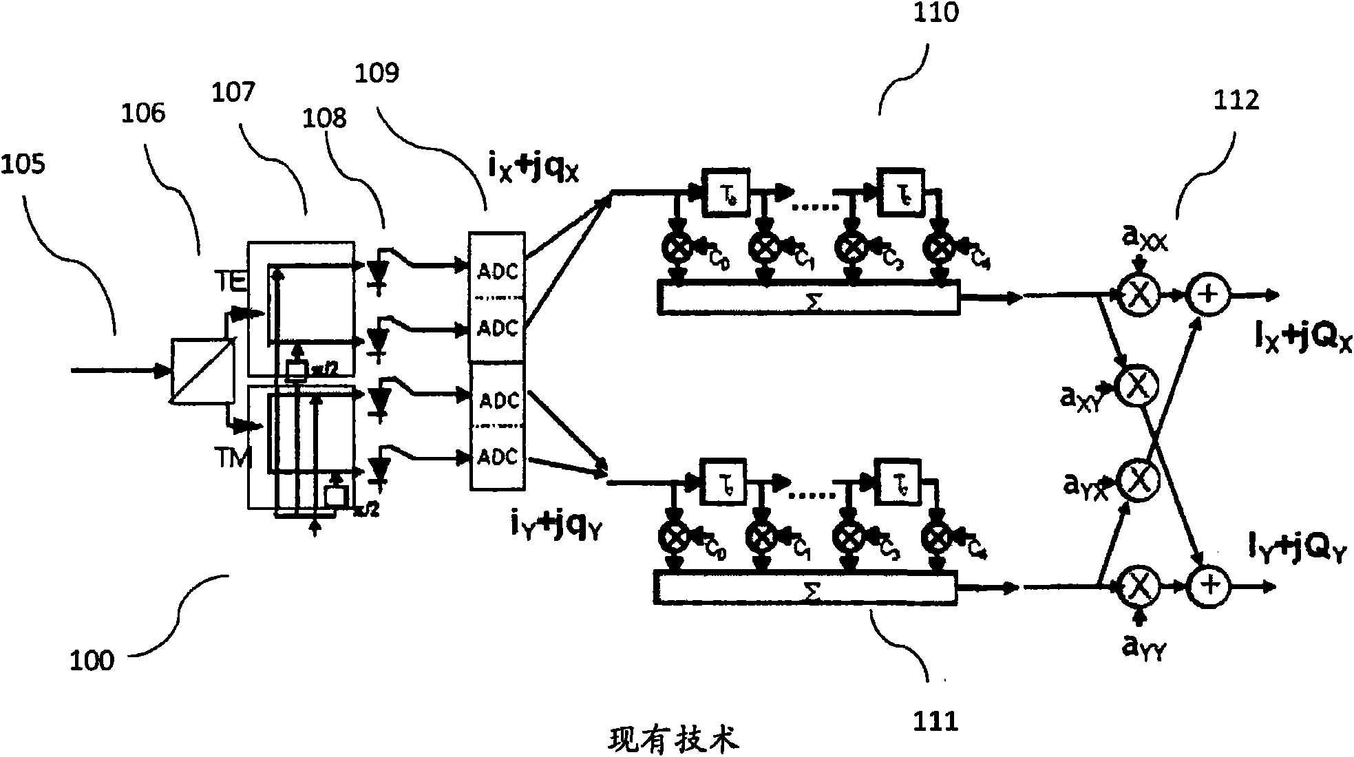
[0045] figure 1 This has already been discussed in the background section of this document.

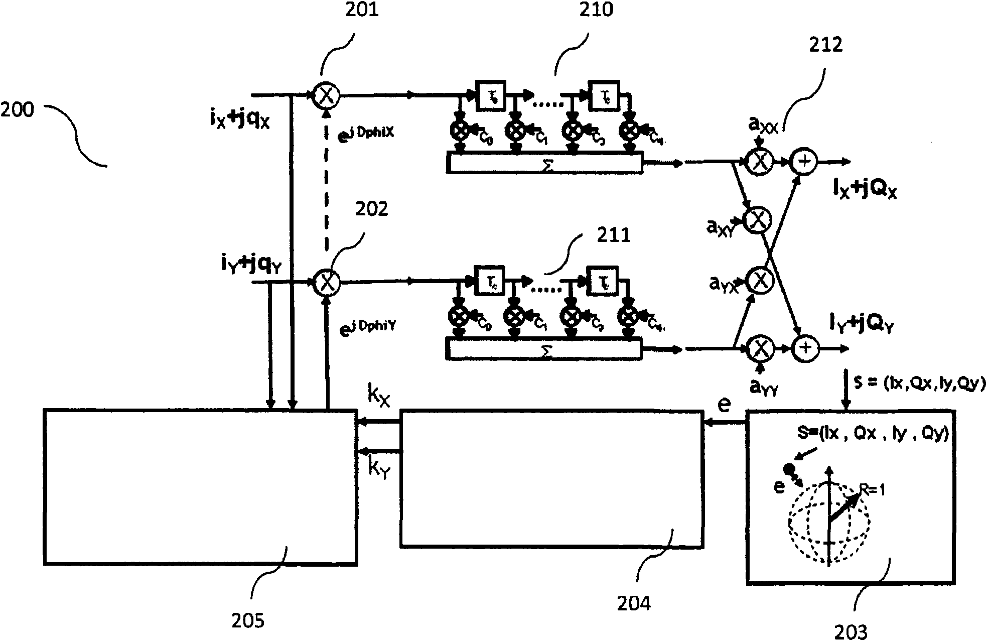
[0046] figure 2 An embodiment of the invention is shown employing self-phase modulation compensation prior to CD equalization. In the example shown, the optical receiver comprises two CD equalizers 210, 211 and one polarization demultiplexer 212 for each signal component. In addition, the optical receiver includes separate signals for each transverse signal component i x +jq x and i y +jq y Phase compensator or phase modulator 201,202. The phase compensator uses the deviation of the signal phase, that is, the phase compensator increases or decreases the signal phase by a phase correction amount or a phase correction value. For the "x" and "y" signal components, the phase correction amount or phase correction value is respectively DphiX and DphiY.

[0047] According to one aspect of the present invention, the following formula can be used to determine the phase correction valu...


PUM


Abstract

The invention relates to optical communication, in particular to compensation of non-linear distortions incurred in high bit-rate optical communication systems. A method and system for compensating self-phase modulation at an optical receiver of an optical transmission system using polarization division multiplexing and a modulation scheme with constant amplitude is proposed. The method comprises the step of performing a phase modulation on a received signal, wherein the received signal comprises two signal components associated with two orthogonal polarizations, each component comprising an in-phase sub-component and a quadrature-phase sub-component, thereby spanning a four-dimensional space. The phase modulation is determined by evaluating an error signal which depends on the distance in the four-dimensional space between the received signal after the phase modulation and a four-dimensional sphere defined by target constellation points of the optical transmission system.

Description

technical field [0001] The present invention relates to optical communication, and more particularly to compensation for nonlinear distortion generated in high bit rate optical communication systems. Background technique [0002] In the prior art, the optical transmission scheme of polarization division multiplexing (PDM) using two independent phase modulation signals (for example, two QPSK (Quadrature Phase Shift Keying) signals) has advantages compared to the non-polarization diversity transmission scheme Higher spectral efficiency. In a coherent receiver, this PDM signal can be demultiplexed and compensated for distortion by means of digital signal processing. Next generation transponders for terrestrial networks expected to use 40Gb / s and 100Gb / s bit rates will be based on polarization multiplexed QPSK (PDM-QPSK) modulation and coherent detection schemes. Using this technology, through digital signal processing (DSP) in the optical receiver, it will be possible to achi...

Claims


Application Information

Patent Timeline
Patent Type & Authority Applications(China)
IPC IPC(8): H04L27/00H04L27/01H04L27/38H04B10/61H04B10/69
CPCH04B10/6161H04B10/6971H04B10/6165H04B10/61H04B10/2507H04B10/255
Inventor H·比洛
Owner ALCATEL LUCENT SAS
Why Eureka
Try Eureka