Unlike digital components, analog components achieve only limited accuracy.
Moreover, even poor levels of analog accuracy tend to be relatively expensive, and greater accuracy is achieved only at even greater expense.
Two other recent trends are the use of modulation forms that require
linear amplification and the use of less expensive, but also less accurate, analog components.
A
linear power amplifier is an analog component that is one of the most expensive and also most power-consuming devices in the transmitter.
One type of power-
amplifier distortion that has received considerable attention is nonlinearity.
Nonlinearity is particularly troublesome in an RF transmitter because it causes spectral regrowth.
Consequently, spectral regrowth would typically cause a transmitter to be in violation of regulations.
Not only does this solution require the use of a more-expensive, higher-power
amplifier, but it also usually requires operating the power
amplifier in a less efficient operating range, thereby causing the transmitter to consume more power than it might if the amplifier were operated more efficiently.
This problem becomes much more pronounced when the communications signal exhibits a
high peak-to-average
power ratio, such as when several digital communications signals are combined prior to amplification.
While prior digital predistorting techniques have achieved some successes, those successes have been limited, and the more modern regulatory requirements of tighter spectral-regulatory masks are rendering the conventional
predistortion techniques inadequate.
But in many of the more accurate, and usually more expensive, conventional applications, the digital predistorter itself includes one or more look-up-tables whose data serve as the instructions which define the character of the
predistortion the digital predistorter will impart to the communications signal.
At the cost of even greater complexity, prior art techniques in high-end applications attempt to compensate for memory effects.
In order to address memory effects, predistorter design is typically further complicated by including multiple look-up-tables and extensive
processing algorithms to first characterize the memory effects, then derive suitable inverse-transfer functions, and alter predistorter instructions accordingly.
The vast array of conventional predistortion techniques suffers from a variety of problems.
The use of training sequences is particularly undesirable because it requires the use of spectrum for control rather than
payload purposes, and it typically increases complexity.
Generally, increased processing complexity in the path of the feedback signal and in the predistorter design is used to achieve increased accuracy, but only minor improvements in accuracy are achieved at the expense of great increases in processing complexity.
Increases in processing complexity for the feedback signal are undesirable because they lead to increased transmitter expense and increased
power consumption.
Following conventional digital predistortion techniques, the cost of digital predistortion quickly meets or exceeds the cost of using a higher-power amplifier operated at greater backoff to achieve substantially the same result.
Thus, digital predistortion has conventionally been practical only in higher-end applications, and even then it has achieved only a limited amount of success.
More specifically, the processing of the feedback signal suffers from some particularly vexing problems using conventional techniques.
While the inversing operation may be somewhat complex on its own, a more serious problem is that it is sensitive to small errors in the feedback signal.
Even a small error processed through an inversing operation can result in a significantly inaccurate inverse-
transfer function.
To complicate matters, the feedback signal typically exhibits an expanded bandwidth due to the spectral regrowth caused by power
amplifier nonlinearity.
But such high speed, high-resolution A / D's are often such costly, high-power components that they negate any power amplifier
cost savings achievable through digital predistortion in all but the most high-end applications.
But the power of the out-of-band portion of the feedback signal only indirectly describes analog-component distortion, again causing increased errors and reduced accuracy in inverse-transfer functions.
Even when conventional designs use high-speed, high-resolution A / D's to capture feedback signals, they still fail to control other
sources of error that, after an inversion operation, can lead to significant inaccuracy in an inverse-transfer-function.
Phase jitter in clocking the A / D adds to error, as does any analog processing that may take place prior to A / D conversion.
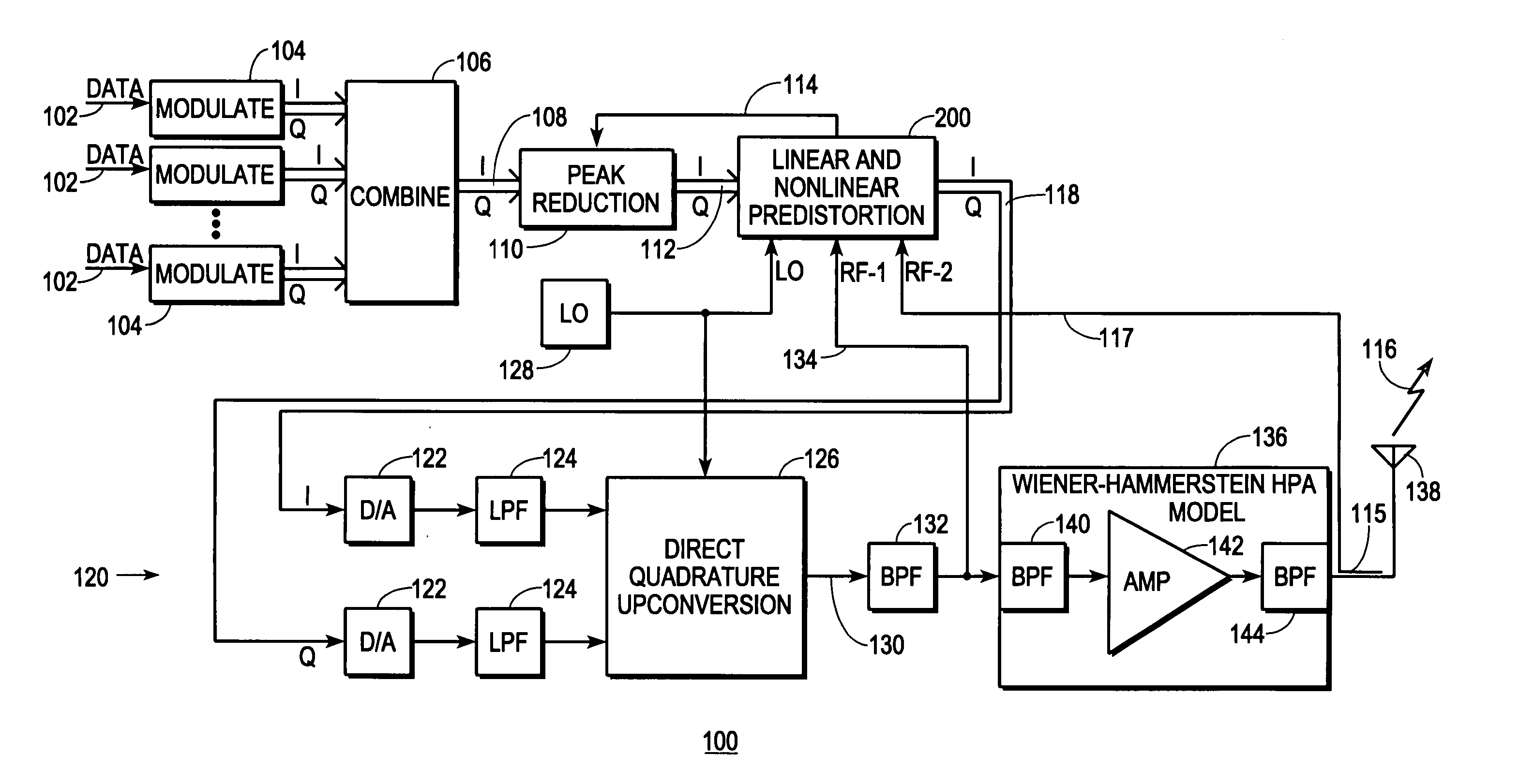
And, conventional practices call for digital communications signals to be complex signals having in-phase and quadrature components which are conventionally processed separately in the feedback signal prior to A / D conversion.
Any quadrature imbalance introduced in the feedback signal by analog processing leads to further error that, after an inversion operation, can cause significant inaccuracy in an inverse-
transfer function.
Linear distortion introduced into the communications signal by analog components is believed to be another source of error that plagues conventional digital predistortion techniques.
But using a
receiver to specify the corrective action that a transmitter should take to reduce linear distortion is undesirable because it does not separate channel-induced distortion from transmitter-induced distortion.
Since multipath usually asserts a dynamic influence on a transmitted RF communications signal as the signal propagates through a channel, such efforts are usually unsuccessful.
In addition, it wastes spectrum for transmitting
control data rather than
payload data, and it requires a
population of receivers to have a compatible capability.
Not only is the failure to address linear distortion in conventional transceivers a problem in its own right, but it is believed to lead to further inaccuracy in characterizing nonlinear transfer functions.
But the use of linearly-distorted signals to derive transfer functions based upon such models, and particularly over wide bandwidths, can violate the controlled conditions.
Consequently, the transfer functions derived therefrom are believed to be less accurate than they might be, and any inverse-transfer functions calculated for use in a digital predistorter can be significantly inaccurate as a result.

