Hoist

A hoist and motor technology, applied in the field of hoist, can solve the problems of increased number of heat sink 120 parts, deterioration of heat dissipation, and increased cost

Active Publication Date: 2010-01-27
KITO CORP
View PDF3 Cites 7 Cited by
  • Summary
  • Abstract
  • Description
  • Claims
  • Application Information

AI Technical Summary

Problems solved by technology

However, this method also has the problems of increasing the size of the resistor 110 including the heat sink 120, especially the increase in height.
In addition, when the contact state between the heat sink 120 and the resi

Method used


Image

  • Hoist
  • Hoist
  • Hoist

Examples


Embodiment Construction

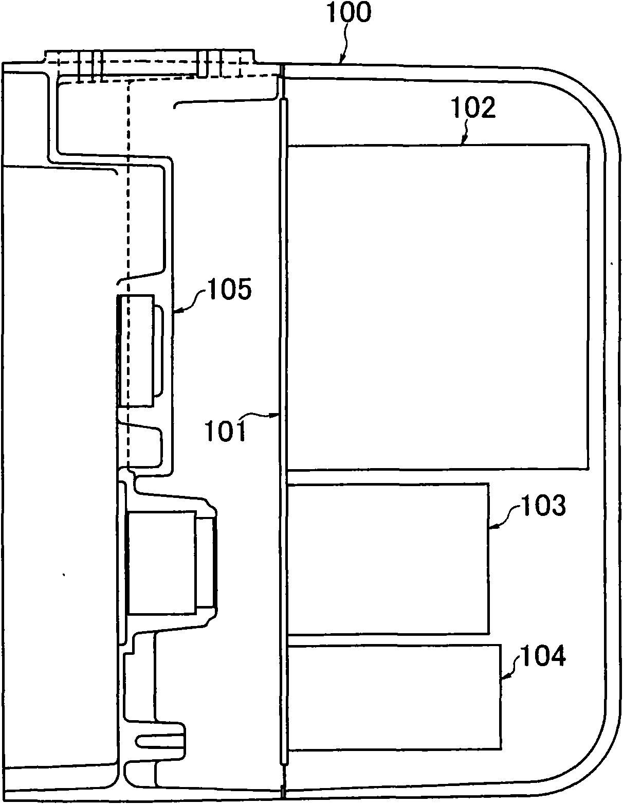
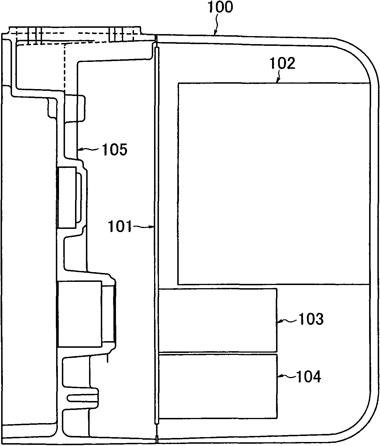
[0053] Hereinafter, embodiments of the present invention will be described with reference to the drawings. Figure 5 It is a plan sectional view showing an example of the internal structure of the control box of the electric chain block of the present invention. As shown in the figure, the inverter 12 is directly mounted on the reduction mechanism housing 15 . At this time, the contact surfaces of the inverter 12 and the speed reduction mechanism case 15 are formed flat with each other, and both are mounted in close contact (in close contact with each other). The reduction mechanism case 15 is formed by aluminum die-casting, and lubricating oil (not shown) for lubricating gears and the like (not shown) constituting the reduction mechanism is housed in the reduction mechanism case 15 .

[0054] In addition, an electromagnetic switch 13 and a transformer 14 mounted on a steel panel 11 are arranged in the control box 10 . In the case of high-frequency operation of the electric ...


PUM


Abstract

A hoist capable of high frequency operation by efficiently releasing heat of an inverter, which is incorporated in a hoist body, to ambient air by using a simple structure. The hoist has a load lifting and lowering electric motor and a reduction gear mechanism, and the motor is driven by the inverter (12) incorporated in the hoist body. The hoist further has heat release means for releasing heat emitted from the inverter (12) to a reduction gear mechanism casing (15). The heat release mechanism is installation means for installing the inverter (12) on the reduction gear mechanism casing (15) with at least a part of the inverter (12) made to be in direct intimate surface contact with the casing (15).

Description

technical field [0001] The present invention relates to a hoist such as an electric chain block or an electric elevator with a built-in electric motor for lifting goods and driven by an inverter. In particular, it relates to a hoist capable of efficiently dissipating the heat generated by the inverter to the outside air and dissipating heat caused by the lifting motor of the goods. The heat generated by the regenerative current flowing through the resistor for regenerative braking during regenerative braking is efficiently dissipated to the outside air, enabling high-frequency operation of the hoist. Background technique [0002] There are known hoisting machines such as an electric chain block and an electric elevator using an inverter-driven motor built in a hoisting machine body as a motor for lifting and lowering goods and driven by an inverter. In this type of hoist, for safety, when the temperature of the frequency converter exceeds a predetermined set temperature, the...

Claims


Application Information

Patent Timeline
IPC IPC(8): B66D1/28B66D1/12H01C1/08H02P3/18
Inventor 石川一光西川和弘
Owner KITO CORP
Why Eureka
Try Eureka