Splicing display system capable of removing splicing black lines of back projection units

A splicing display and rear projection technology, applied in optics, instruments, projection devices, etc., can solve problems such as image segmentation, and achieve the effect of eliminating image splicing seams and black lines

Inactive Publication Date: 2011-06-29
GUANGDONG VTRON TECH CO LTD
View PDF0 Cites 2 Cited by
  • Summary
  • Abstract
  • Description
  • Claims
  • Application Information

AI Technical Summary

Problems solved by technology

Because no projected light reaches the stitching seam 12, a black line is formed at the stitching seam 12 on the stitched image, resulting in image segmentation

Method used


Image

  • Splicing display system capable of removing splicing black lines of back projection units
  • Splicing display system capable of removing splicing black lines of back projection units
  • Splicing display system capable of removing splicing black lines of back projection units

Examples


Embodiment

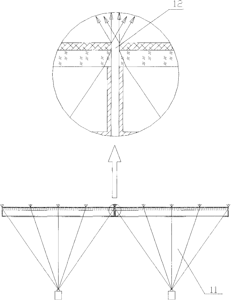
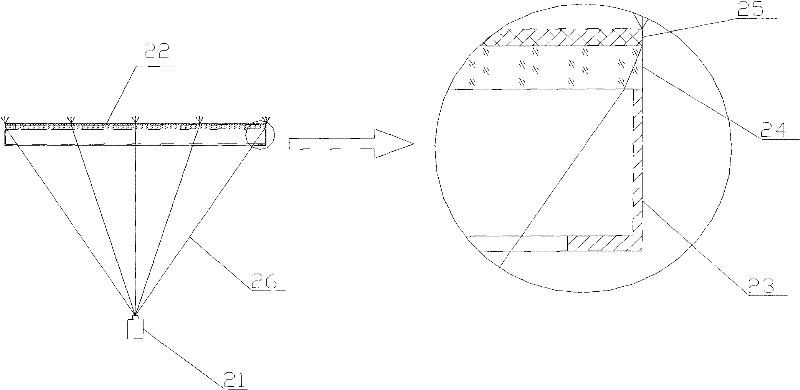
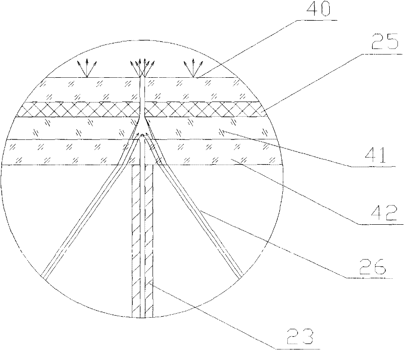
[0030] The structure of the present invention is as image 3 As shown, the entire splicing display system is composed of multiple rear projection units spliced ​​with each other, and there is a splicing seam between two adjacent rear projection units. Wherein each rear projection unit is composed of a projector and a screen system arranged sequentially according to the optical path. The screen system includes a fixed bracket 23, and an outer glass plate 40, a rear projection screen 25, a Fresnel lens 41, and a light-transmitting plate 42 fixedly connected in sequence, wherein the light-transmitting plate 42 is arranged on the inside of the Fresnel lens 41 and installed on the Between the Fresnel lens 41 and the fixed bracket 23 . The Fresnel lenses 41 correspond to the projectors one by one, and the projection range of each projector is aligned with its corresponding Fresnel lens; the Fresnel lenses of two adjacent screen systems are spliced ​​together. In this embodiment, t...


PUM


Abstract

The invention provides a splicing display system capable of removing splicing black lines of back projection units, wherein a splicing slot exists between adjacent two back projection units; each back projection unit comprises a projector and screen systems which are sequentially arranged according to a light path; the screen system comprises Fresnel Lenses and a back projection screen; the Fresnel Lenses of adjacent two screen systems are mutually spliced; the range of rays projected by the projector slightly exceeds a display image range of the back projection screen; the exceeding rays areprojected on the side surfaces of the screen systems and the mutually spliced side surfaces of the Fresnel Lenses are provided with cutting angels which do not influence the refraction and the transmission of the display image edge of the front surface of the screen in the Fresnel Lenses. The splicing display system leads a small number of rays on the projection edges into the splicing slot and emits the rays to the front surface of the screen from the splicing slot, thereby removing the splicing slot of images on a splicing display screen and realizing the integral display of splicing images.

Description

technical field [0001] The invention relates to the field of rear projection splicing display, in particular to a splicing display system capable of eliminating splicing black lines of rear projection units. Background technique [0002] The projection splicing display wall is a special projection display application, which splices the images of multiple display units together to realize super-large screen ultra-high-resolution image display. Due to the advancement of technology, the image seam of the current video wall has been made very small, less than one pixel of the image, and there is almost no loss of image. Even so, there are still obvious stitching seams between adjacent units, and there is an obvious black line visually, which shows that the image has a feeling of being split, which affects the overall display effect of the image, and has not achieved the real meaning seamless mosaic. [0003] The structure of the usual projection unit splicing display system is...

Claims


Application Information

Patent Timeline
Patent Type & Authority Patents(China)
IPC IPC(8): G03B21/56G03B21/00
Inventor 孟凡华梁明浩卢如西罗振华
Owner GUANGDONG VTRON TECH CO LTD
Why Eureka
Try Eureka