Seamless splicing method of back projection unit and special optical structure
An optical structure, seamless splicing technology, applied in optics, instruments, projection devices, etc., can solve problems such as image segmentation, and achieve the effect of simple structure, favorable for popularization and application, and less cost increase
- Summary
- Abstract
- Description
- Claims
- Application Information
AI Technical Summary
Problems solved by technology
Method used
Image
Examples
Embodiment 1
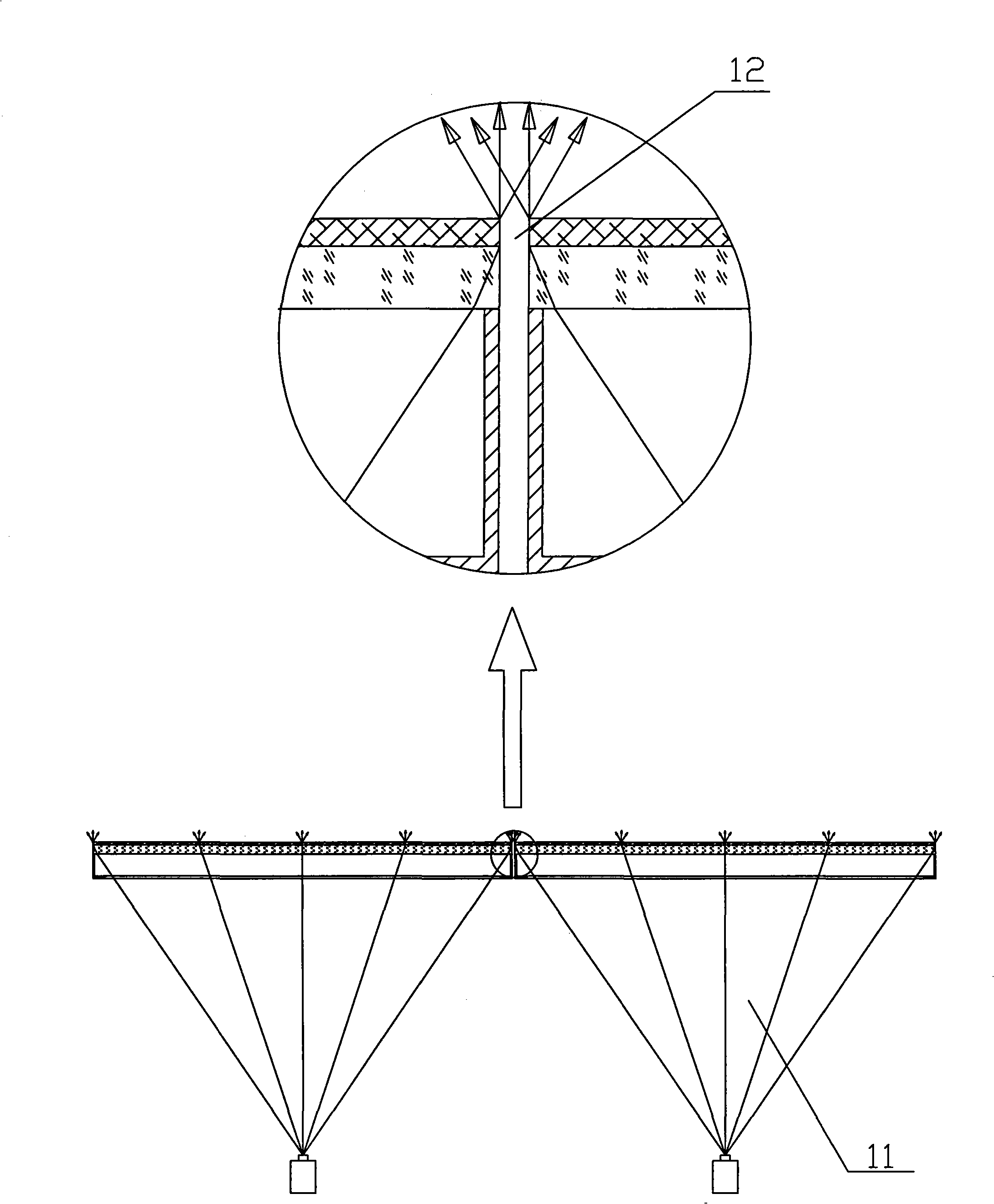
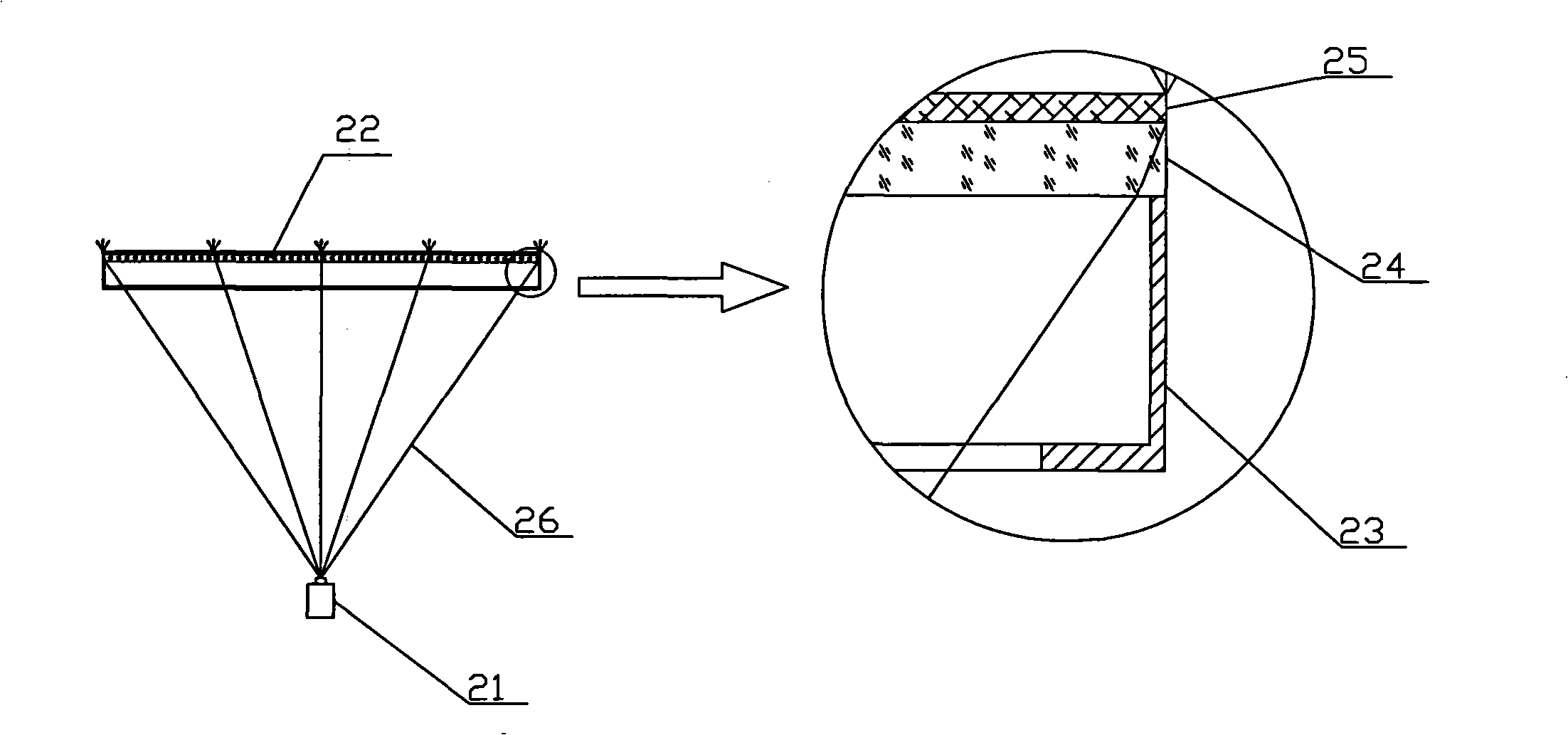
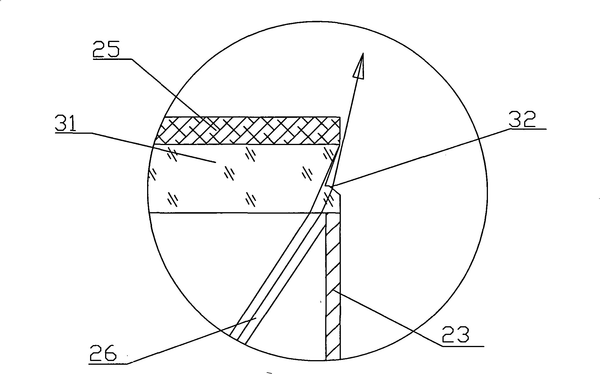
[0030] The optical structure used in this embodiment is as image 3 As shown, the overall splicing structure is as Figure 7 As shown, the entire splicing display system is mainly composed of multiple rear projection units 11 spliced with each other, and there is a splicing gap 12 between two adjacent rear projection units. Each rear projection unit 11 is composed of a projector 21 and a screen system 22 arranged in sequence according to the optical path. The screen system 22 is mainly composed of a fixed bracket 23 , a Fresnel lens 31 and a rear projection screen 25 arranged in sequence according to the optical path. Groove 32 is made on the Fresnel lens 31, and the surface of groove 32 can be smooth surface, also can be frosted surface, and the opening of groove 32 points to outside, and groove is close to the inclined surface of screen and the front of Fresnel lens. The included angle is greater than the angle corresponding to the edge light of the image displayed on th...
Embodiment 2
[0033] The optical structure used in this embodiment is as Figure 4 As shown, the overall splicing structure is as Figure 8 As shown, the entire splicing display system is mainly composed of multiple rear projection units 11 spliced with each other, and there is a splicing gap 12 between two adjacent rear projection units. Each rear projection unit 11 is composed of a projector 21 and a screen system 22 arranged in sequence according to the optical path. The screen system 22 is mainly composed of a fixed bracket 23 , a Fresnel lens 41 , a glass plate 42 and a rear projection screen 25 arranged in sequence according to the optical path, wherein the glass plate 42 is installed between the Fresnel lens 41 and the fixed bracket 23 . A cut corner 43 and a cut corner 44 are respectively provided on the edges of the surface of the Fresnel lens 41 in contact with the glass plate 42 , and the two cut corners constitute the optical structure of this embodiment. The included angle ...
Embodiment 3
[0036] The optical structure used in this embodiment is as Figure 5 As shown, the overall splicing structure is as Figure 9 As shown, the entire splicing display system is mainly composed of multiple rear projection units 11 spliced with each other, and there is a splicing gap 12 between two adjacent rear projection units. Each rear projection unit 11 is composed of a projector 21 and a screen system 22 arranged in sequence according to the optical path. The screen system 22 is mainly composed of a fixed bracket 23 , a Fresnel lens 24 and a rear projection screen 25 arranged in sequence according to the optical path. A scattering layer 51 or a light-transmitting microstructure layer 52 is formed on the side of the Fresnel lens 24 . The scope of the light 26 projected by the projector 21 in this embodiment is expanded relative to the prior art, and slightly exceeds the scope of the display image on the rear projection screen 25, and the excess light is projected onto the ...
PUM
 Abstract
Description
Claims
Application Information
 - R&D
- Intellectual Property
- Life Sciences
- Materials
- Tech Scout
- Unparalleled Data Quality
- Higher Quality Content
- 60% Fewer Hallucinations
Browse by: Latest US Patents, China's latest patents, Technical Efficacy Thesaurus, Application Domain, Technology Topic, Popular Technical Reports.
© 2025 PatSnap. All rights reserved.Legal|Privacy policy|Modern Slavery Act Transparency Statement|Sitemap|About US| Contact US: help@patsnap.com


