
Apparatus for moving camera

A technology for moving cameras and equipment, applied in image communication, parts of color TVs, parts of TV systems, etc., can solve the problems of not being able to stop the movement of the camera instantaneously, difficult to change the direction of movement of the camera, and limited speed of movement of the camera.

Inactive Publication Date: 2010-03-10
李应俊
View PDF0 Cites 0 Cited by
  • Summary
  • Abstract
  • Description
  • Claims
  • Application Information

AI Technical Summary

Problems solved by technology

[0004] However, the use of cables or wires to move the camera has the following disadvantages: the camera needs to be supported by the cables or wires, the moving speed of the camera is limited, it is difficult to change the moving direction of the camera, the movement of the camera cannot be stopped instantaneously, and additional manpower is required pulling a cable or wire

Method used


Image

  • Apparatus for moving camera
  • Apparatus for moving camera
  • Apparatus for moving camera

Examples


Embodiment Construction

[0029] Hereinafter, preferred embodiments of the present invention will be described in detail with reference to the accompanying drawings. Before the description is made, it should be understood that the terms used in the specification and appended claims should not be construed as limited to their ordinary and literal meanings, but should be interpreted according to the principles that allow the inventor to properly define the terms, It is interpreted based on meanings and concepts corresponding to the technical aspects of the present invention. Therefore, the description presented here is only for the purpose of illustrating the preferred examples and is not intended to limit the scope of the invention, so it should be understood that other equivalents can be made to the invention without departing from the spirit and scope of the invention. Variations and improvements.

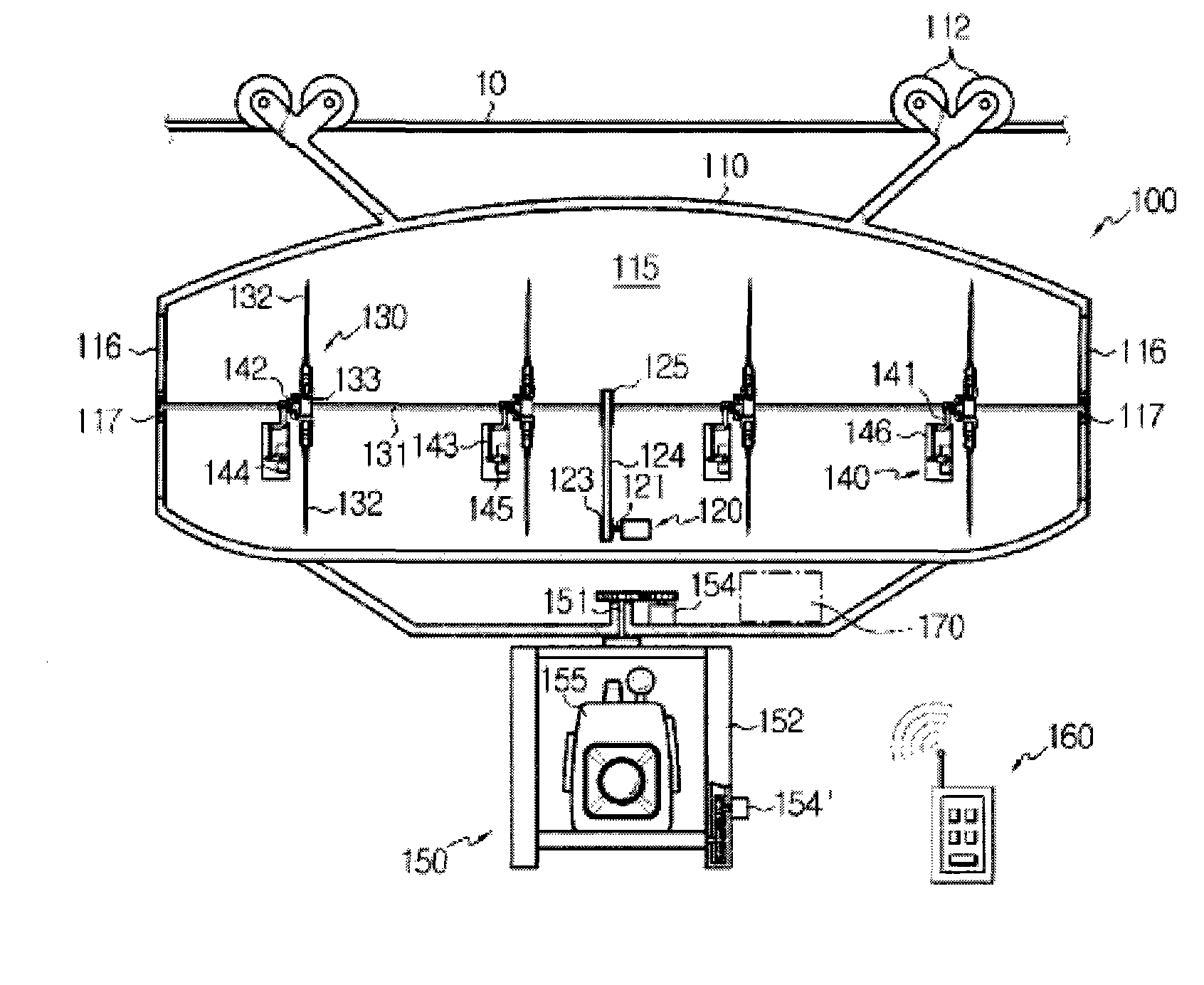
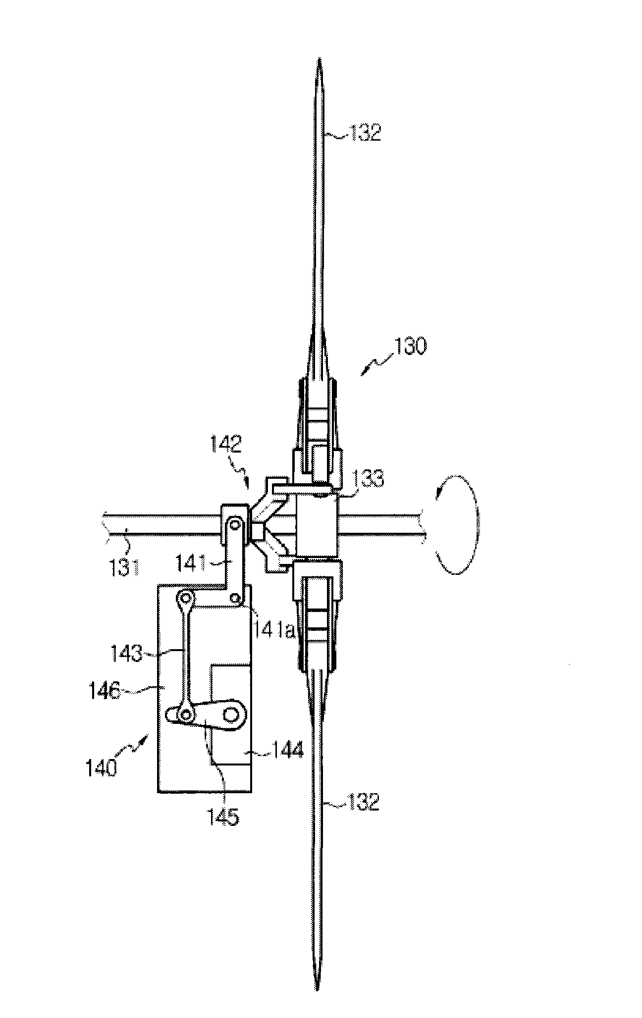
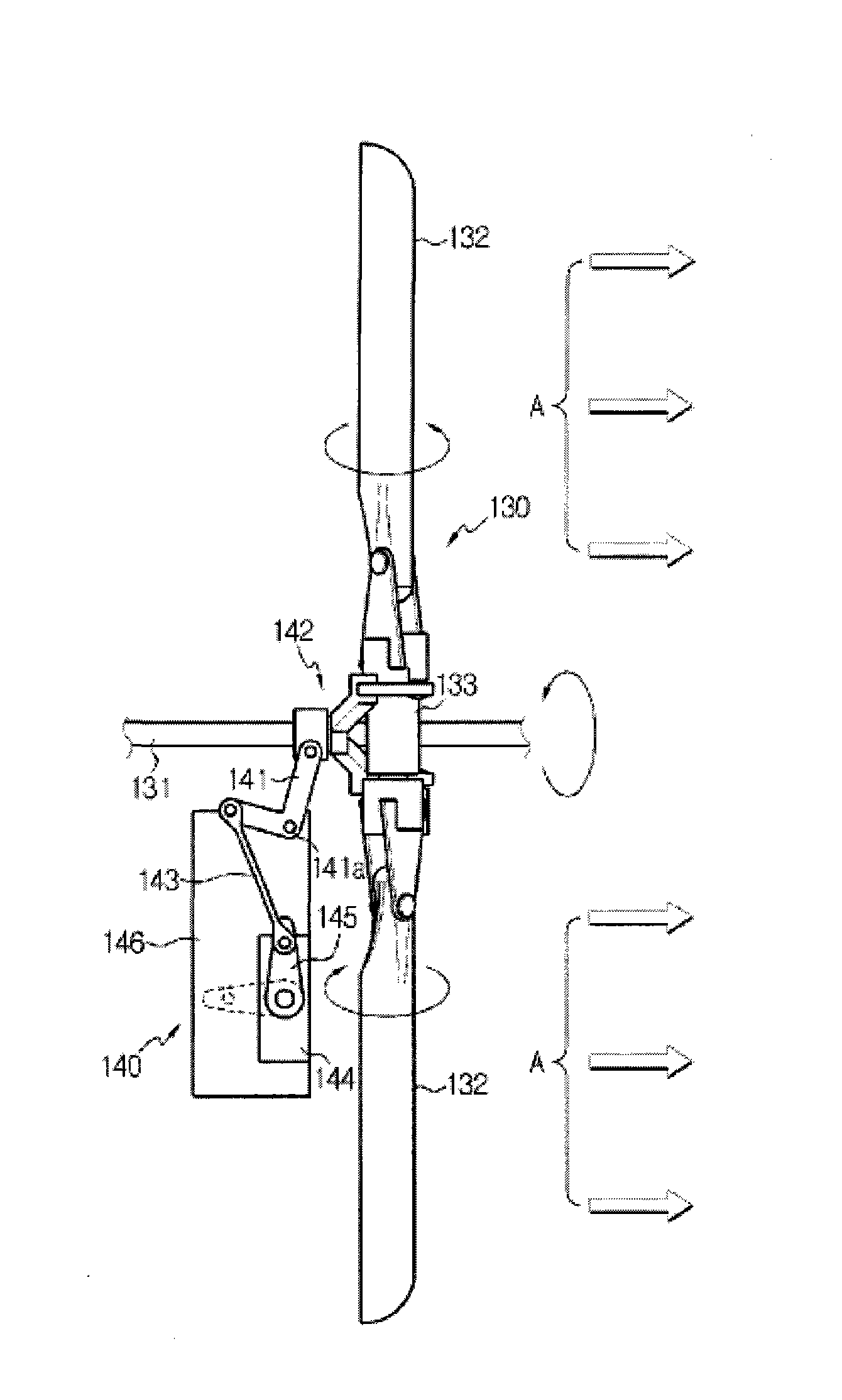
[0030] figure 1 A partial sectional view of a camera moving device according to a first embodiment of...


PUM


Abstract

The present invention relates to a camera moving apparatus, and in particular to a camera moving apparatus, which can rapidly move a camera held on a cable or wire using a propeller and move the camera vertically and horizontally to improve a photographing range and rapidly change a moving direction of the camera.

Description

technical field [0001] The present invention relates to a camera moving device, more specifically, to a camera moving device, which can quickly move a camera supported on a cable or steel cable by using a propeller, and can quickly change the moving direction of the camera. Background technique [0002] As we all know, video cameras are used to film objects in sports, movies, plays or advertisements. Generally speaking, the camera shoots static objects, but in some cases, for special scenes, the camera also shoots moving objects. [0003] To move the camera quickly, pull the cable or wire that supports the camera. [0004] However, moving the camera with a cable or a wire rope has the following disadvantages: the camera needs to be supported by the cable or wire rope, the moving speed of the camera is limited, it is difficult to change the moving direction of the camera, the movement of the camera cannot be stopped instantaneously, and additional manpower is required Pull ...

Claims


Application Information

Patent Timeline
IPC IPC(8): H04N5/225
CPCH04N7/185H04N23/00
Inventor 李应俊
Owner 李应俊
Learn More