Powder paving device

A powder spreading device and powder spreading technology, applied in the direction of additive processing, etc., can solve the problems of low powder spreading efficiency, achieve the effect of improving powder laying efficiency, avoiding bridging, and improving powder spreading efficiency

Active Publication Date: 2020-07-31
HANS LASER TECH IND GRP CO LTD +1
View PDF6 Cites 1 Cited by
  • Summary
  • Abstract
  • Description
  • Claims
  • Application Information

AI Technical Summary

Problems solved by technology

[0005] The technical problem to be solved by the present invention is to provide a new type of powder spreading device to overcome the defects of low powder spreading efficiency of the existing powder spreading device in view of the above-mentioned defects of the prior art

Method used


Image

  • Powder paving device
  • Powder paving device
  • Powder paving device

Examples


Embodiment Construction

[0026] Now in conjunction with the accompanying drawings, the preferred embodiments of the present invention will be described in detail.

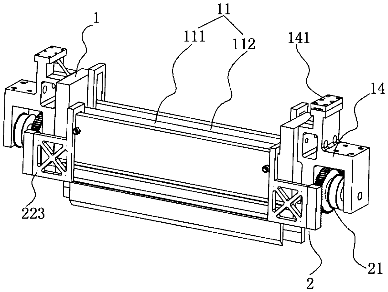
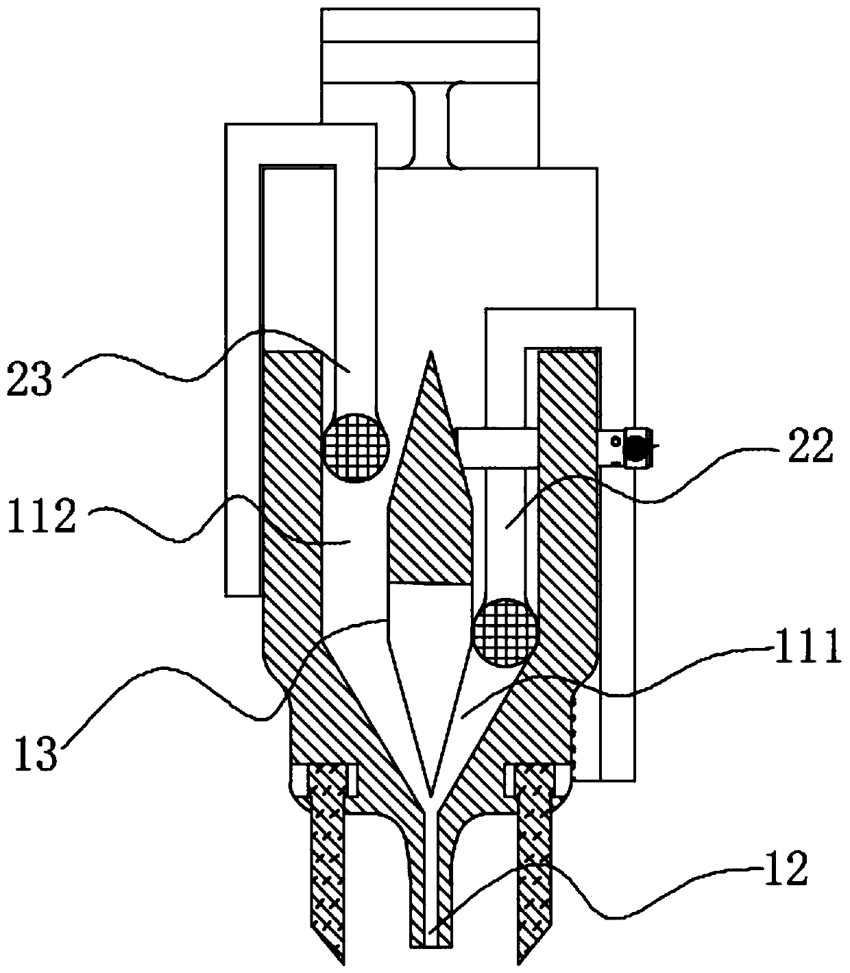
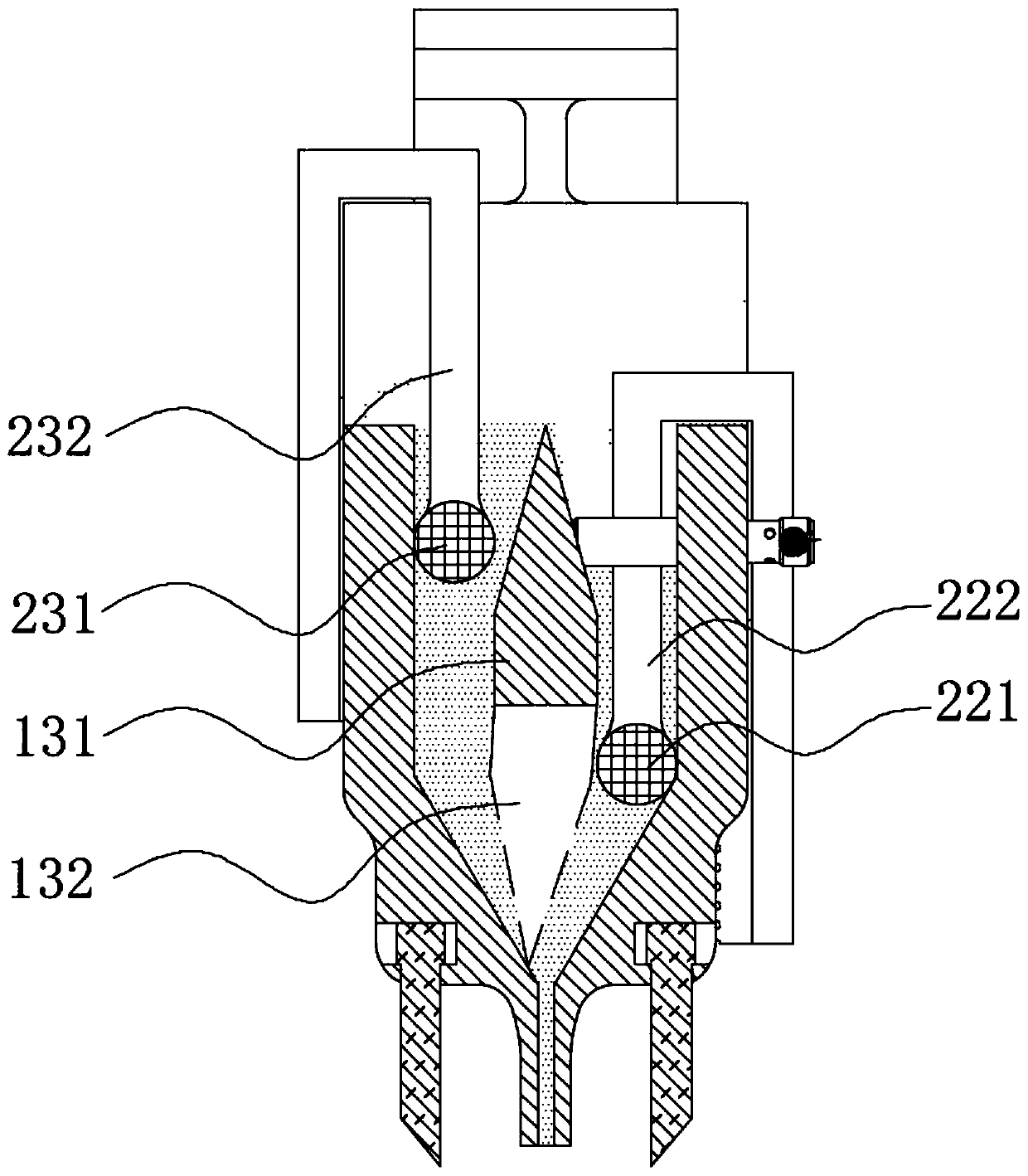
[0027] Such as figure 1 and figure 2 As shown, the powder spreading device of the present invention includes a powder spreading box 1 and a powder pushing mechanism 2 . The powder spreading box 1 has a powder storage chamber 11 and a first powder outlet 12, the powder storage chamber 12 is provided with a partition 13, and the partition 13 divides the powder storage chamber 11 into a first powder storage tank 111 and a second powder storage tank 112 , the partition 13 can switch the communication between the first powder storage tank 111 and the second powder storage tank 112 and the first powder outlet 12 . The powder pusher mechanism 2 includes a power input mechanism 21 and a first powder pusher 22 and a second powder pusher 23 respectively movably arranged in the first powder storage tank 111 and the second powder storage tank 112 ....


PUM


Abstract

The invention relates to a powder paving device. A powder paving box with a powder storage cavity and a powder pushing mechanism are included. The powder storage cavity is internally provided with a partition plate for dividing the powder storage cavity into a first powder storage groove and a second powder storage groove. The powder pushing mechanism comprises a power input mechanism, a first powder pushing piece and a second powder pushing piece. The first powder pushing piece and the second powder pushing piece are arranged in the first powder storage groove and the second powder storage groove, when the power input mechanism drives the first powder pushing piece to downwards move, the partition plate closes the second powder storage groove, and powder flows out of the first powder groove under thrust of the first powder pushing piece. When the power input mechanism drives the second powder pushing piece to downwards move, the partition plate closes the first powder storage groove,and powder flows out of the second powder groove under thrust of the second powder pushing piece. Powder flows out of a first powder outlet under the action of thrust of the first powder pushing pieceor the second powder pushing piece, and therefore the powder discharging efficiency can be improved, and the bridging phenomenon can be avoided as well.

Description

technical field [0001] The invention relates to the technical field of 3D printing processing, in particular to a powder spreading device. Background technique [0002] 3D printing technology is a technology that accumulates materials layer by layer to manufacture solid workpieces. Compared with traditional material removal technology, it does not require tools and molds, and does not require multi-process processing. The production cycle is short and complex structures can be easily processed. artifacts. [0003] At present, in the field of 3D printing manufacturing, common powder spreading methods include scraper type and moving hopper type. Scraper-type powder spreading, the material is discharged at one end of the cylinder, and then the metal powder is pushed by the scraper to scrape from one end of the cylinder to the other. If this method is used to spread the powder, when the scraper moves too fast, the powder will be taken away by the scraper, resulting in uneven p...

Claims


Application Information

Patent Timeline
Patent Type & Authority Applications(China)
IPC IPC(8): B22F3/00B33Y30/00B22F12/50B22F12/60
CPCB22F3/003B33Y30/00
Inventor 刘旭飞李清刘鹏宇何菊翠陈根余陈焱高云峰
Owner HANS LASER TECH IND GRP CO LTD
Why Eureka
Try Eureka