

Drive method of photoelectric display device
A technology of photoelectric display and driving method, which is applied in the field of driving to achieve the effect of reducing discomfort
- Summary
- Abstract
- Description
- Claims
- Application Information
AI Technical Summary
Problems solved by technology
Method used
Image

Examples
Embodiment Construction
[0041] In order to further explain the technical means and effects that the present invention adopts to achieve the intended purpose of the invention, the specific implementation, steps, features and details of the driving method of the optoelectronic display device proposed according to the present invention will be described below in conjunction with the accompanying drawings and preferred embodiments. Its effect is described in detail below.
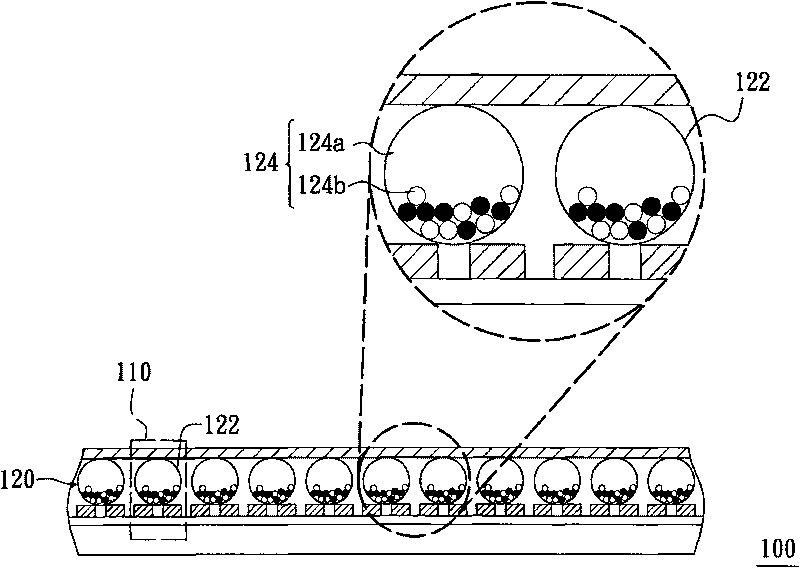
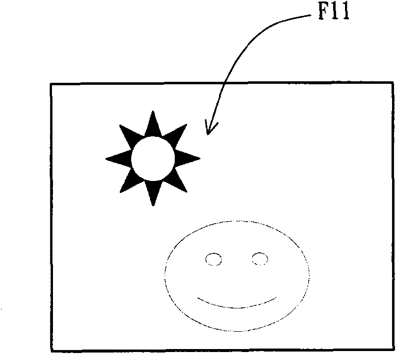
[0042] see Image 6 , Figure 7 and Figure 8 as shown, Image 6 is a schematic cross-sectional view of an optoelectronic display device according to an embodiment of the present invention, Figure 7 Yes Image 6 A schematic diagram of the different gray levels presented by one of these pixels at different times, Figure 8 is a schematic diagram of a driving method of an optoelectronic display device in this embodiment. An optoelectronic display device 300 according to an embodiment of the present invention has a plurality of pi...
PUM
 Abstract
Description
Claims
Application Information