
Junction box fixing device and junction box

A fixing device and junction box technology, applied in the direction of electrical components, etc., can solve the problems of decreased firmness, inconvenient operation, and weak fixing, and achieve the effect of reducing installation, reducing damage, and being convenient and firm to fix.

Inactive Publication Date: 2010-06-09
吴连祥
View PDF1 Cites 6 Cited by
  • Summary
  • Abstract
  • Description
  • Claims
  • Application Information

AI Technical Summary

Problems solved by technology

[0002] Cable or optical cable junction boxes are widely used in the wiring of cables or optical cables. During use, they need to be fixed on the wall. When the wall is thin or not very strong, the junction box is not fixed firmly. To solve the above technical problems, the patent The Chinese utility model patent No. "98223332.9" and titled "A Low-Strength Wall Surface Junction Box Fixer" discloses a junction box fixing device, which includes a base, which is a "U"-shaped thin plate , A through hole is provided at the two upward ports of the "U"-shaped thin plate, a buckle is arranged upward on the inner side of the bottom center of the "U"-shaped thin plate, and a downward embedding groove is set on the top inner side of the buckle. Although the fixture can fix the junction box on the low-strength wall, it still has the following disadvantages: the fixation is not firm, and one fixture can only fix one junction box. When the junction boxes are concentrated, multiple fixtures are required to fix the junction box. More holes are set on the body, which is inconvenient to operate, and reduces the strength of the thin plate wall, reducing the firmness of the fixation

Method used


Image

  • Junction box fixing device and junction box
  • Junction box fixing device and junction box
  • Junction box fixing device and junction box

Examples


Embodiment Construction

[0026] Below in conjunction with accompanying drawing and embodiment the present invention will be further described:

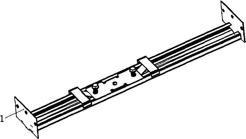
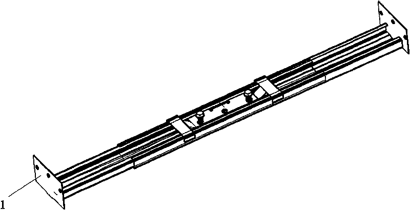
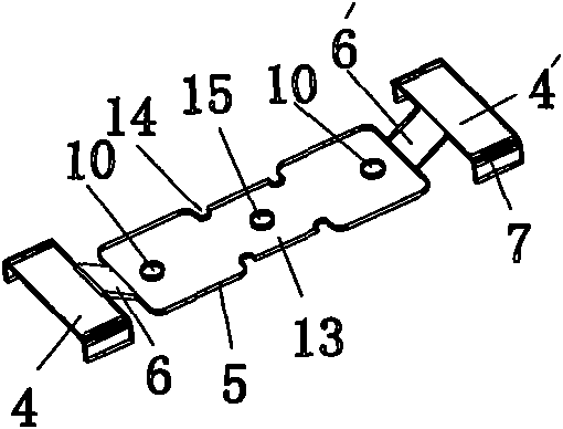
[0027] Such as Figure 1-6 As shown, the junction box fixing device of the present invention is composed of a grooved plate base and a fastening spring piece. Connecting pieces 1 are arranged at both ends of the grooved plate base, and each connecting piece 1 is provided with a connecting hole. The connecting piece 1 can be a fixed The plate can be arranged perpendicular to the base of the channel plate, or it can be arranged parallel to the base of the channel plate. The cross section of the base of the channel plate is U-shaped, and the side walls 2 of the base on both sides are respectively bent inward to form an upper slide rail. 3. A better design is that the bottom of the U-shaped plate is set as a curved surface that is concave in the middle and flat on both sides, that is, the bottom of the U-shaped plate is a flat surface 11 at both ends and a curved...


PUM


Abstract

The invention discloses a junction box fixing device which comprises a substrate. The substrate is a groove-shaped plate base; connecting pieces are arranged on both ends of the base; two substrate side walls of the groove-shaped plate base are inwards bent to form two parallel up slide rails; a fastening spring lamination comprises a left slide part, a right slide part and a middle plane part; the middle plane part is downwards concaved to enable the left slide part, the right slide part and the middle plane part to form a left oblique transition part and a right oblique transition part; the left slide part and the right slide part are both U-shaped groove plates; the side wall of the slide part is arranged at the outer side of the substrate side wall; the middle plane part is arranged in a groove of the groove-shaped plate base, and two sides are positioned above the up sidle rail; and screwed holes are arranged on the middle plane part. The junction box fixing device can fix a plurality of junction boxes, and the fixing is convenient and firm.

Description

technical field [0001] The invention relates to a junction box fixing device and a junction box. Background technique [0002] Cable or optical cable junction boxes are widely used in the wiring of cables or optical cables. During use, they need to be fixed on the wall. When the wall is thin or not very strong, the junction box is not fixed firmly. To solve the above technical problems, the patent The Chinese utility model patent No. "98223332.9" and titled "A Low-Strength Wall Surface Junction Box Fixer" discloses a junction box fixing device, which includes a base, which is a "U"-shaped thin plate , A through hole is provided at the two upward ports of the "U"-shaped thin plate, a buckle is arranged upward on the inner side of the bottom center of the "U"-shaped thin plate, and a downward embedding groove is set on the top inner side of the buckle. Although the fixture can fix the junction box on the low-strength wall, it still has the following disadvantages: the fixatio...

Claims


Application Information

Patent Timeline
Patent Type & Authority Applications(China)
IPC IPC(8): H02G3/10H02G3/08
Inventor 吴连祥
Owner 吴连祥
Learn More