Phase-shifting control method of a boost converter and implementing circuit

A technology of phase-shift control and converter, which is applied in the direction of conversion equipment without intermediate conversion to AC, and can solve the problem that the phase-shift conduction method is difficult to control and work in critical mode.

Active Publication Date: 2010-06-23
SPI ELECTRONICS
View PDF0 Cites 3 Cited by
  • Summary
  • Abstract
  • Description
  • Claims
  • Application Information

AI Technical Summary

Problems solved by technology

[0005] Since the phase-shift conduction method is difficult to control its operation in the critical mode, the shortcomings of the sub-harmonic oscillation generated by the phase-shift off-state method must be improved to improve the efficiency of the parallel boost converter.

Method used


Image

  • Phase-shifting control method of a boost converter and implementing circuit
  • Phase-shifting control method of a boost converter and implementing circuit
  • Phase-shifting control method of a boost converter and implementing circuit

Examples


Embodiment Construction

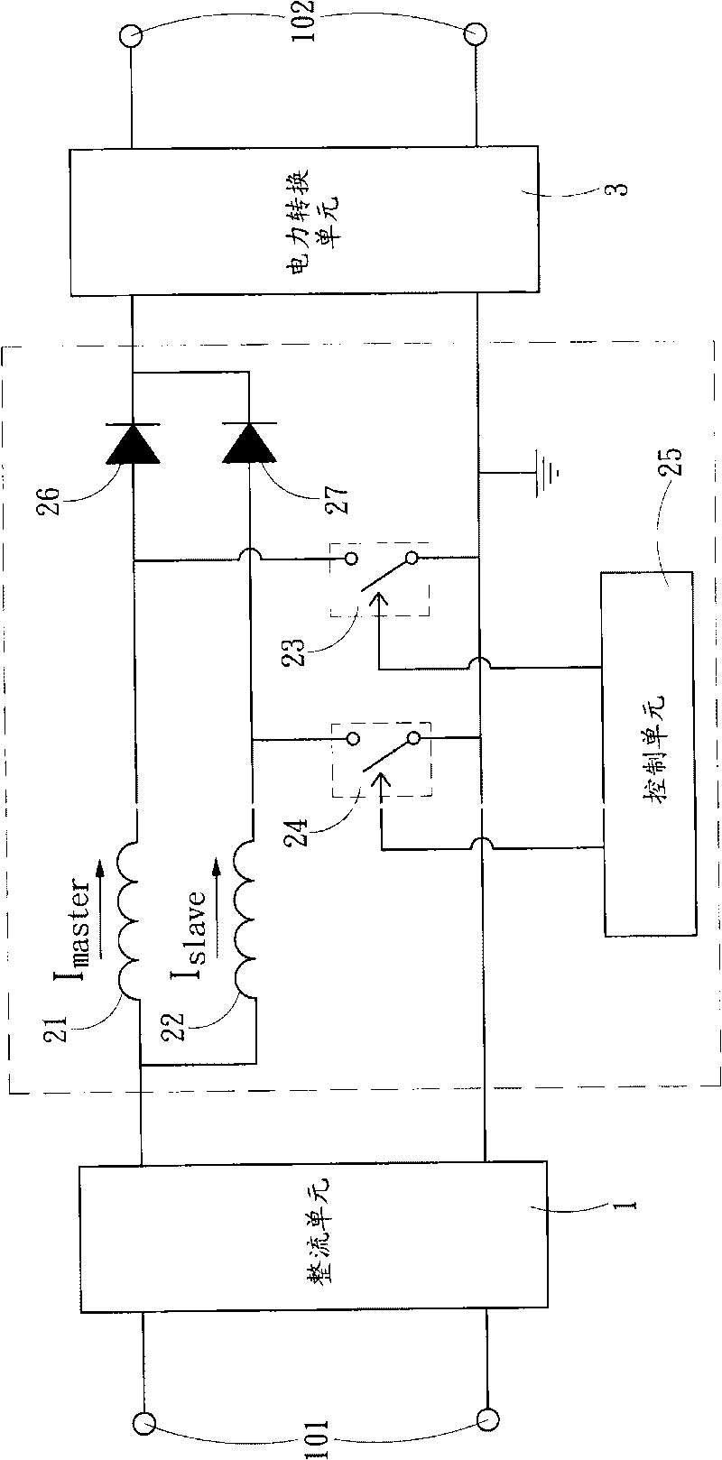
[0016] This case is a phase shift control method and implementation circuit of a boost converter, which is applied to an interleaved parallel boost converter (hereinafter referred to as boost converter 2) in a power supply. Figure 5 As shown, the power supply is connected to the input terminal 101, and the rectification unit 1 is connected to the input terminal 101 to obtain the input power and rectify the output to the boost converter 2, and then send it to the boost converter 2 after being regulated by the boost converter 2. The power conversion unit 3 modulates the rated output power and sends it to the output terminal 102; wherein the step-up converter 2 has a main energy storage circuit and at least one auxiliary energy storage circuit connected in parallel with the main energy storage circuit, and the main energy storage circuit The circuit and the auxiliary energy storage circuit respectively include energy storage coils 21, 22 and diodes 26, 27 connected in series with...


PUM


Abstract

The present invention relates to a phase-shifting control method of a boost converter and an implementing circuit, wherein the boost converter is provided with a main energy storing loop and at least one second energy storing loop connected with the main energy storing loop in parallel; a main loop current passing through the main energy storing loop has main loop charging time distance and main loop discharging time distance; and a second loop current passing through the second energy storing loop has second loop charging time distance and second loop discharging time distance. An ideal switching time sequence of judging value when the second loop current decreases to zero current is calculated, an actual switching time sequence of the second loop charging time distance is started, break-over error time distance of the phase differences of the ideal switching time sequence and the actual switching time sequence is obtained, and the second loop charging time distance is decided by the break-over error time distance and the main loop charging time sequence. Thus, the break-over error time distance of the nest period is avoided to enlarge, and further, a problem that the second loop current generates subharmonic oscillation is avoided.

Description

technical field [0001] The invention relates to a phase shift control method and implementation circuit of a boost converter, in particular to a control method for driving a parallel boost converter to ensure that it works in a critical mode. Background technique [0002] Most of today's power supplies or power adapters provide the function of adjusting voltage through switching converters, and the most common one is boost converters, whose purpose is not only to adjust voltage It can also be seen in the power factor correction circuit, and the power factor of the input power is adjusted by step-up; see figure 1 , figure 1 Shown is the basic structure of the circuit of the parallel boost converter. After the rectification unit 1 is connected to the input terminal 101 to obtain the input power and modulate it into DC, the boost converter 2 modulates the modulated power output to A power conversion unit 3, and the power conversion unit 3 converts the modulated power into the...

Claims


Application Information

Patent Timeline
Patent Type & Authority Applications(China)
IPC IPC(8): H02M3/10
Inventor 徐明陈桥樑尹燕萍白永江杨旭
Owner SPI ELECTRONICS
Why Eureka
Try Eureka