
LED control circuit

A technology for controlling circuits and circuits, applied in circuit layout, lamp circuit layout, electric light source, etc., can solve the problems of low input power factor, narrow input voltage range, insufficient protection function, etc., to prevent damage and prevent over-temperature protection. Effect

Inactive Publication Date: 2010-07-14
OCEANS KING LIGHTING SCI&TECH CO LTD
View PDF3 Cites 30 Cited by
  • Summary
  • Abstract
  • Description
  • Claims
  • Application Information

AI Technical Summary

Problems solved by technology

[0003] The purpose of the embodiment of the present invention is to provide an LED control circuit, aiming at solving the problems of narrow input voltage range, low input power factor and insufficient protection function in the existing LED control circuit

Method used


Image

  • LED control circuit
  • LED control circuit
  • LED control circuit

Examples


Embodiment Construction

[0020] In order to make the object, technical solution and advantages of the present invention clearer, the present invention will be further described in detail below in conjunction with the accompanying drawings and embodiments. It should be understood that the specific embodiments described here are only used to explain the present invention, not to limit the present invention.

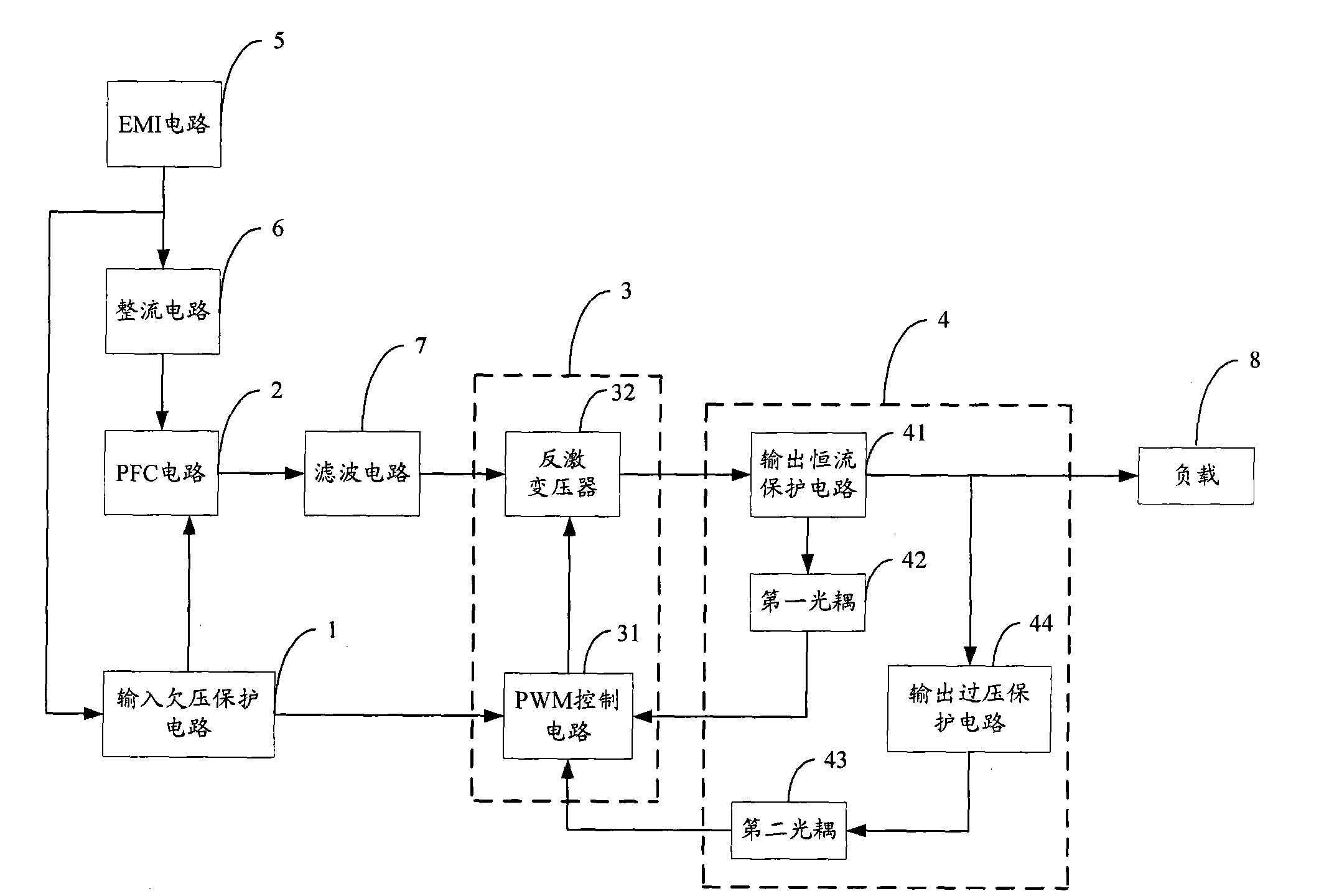
[0021] The module structure of an LED control circuit provided by an embodiment of the present invention is as follows: figure 1 As shown, for ease of description, only the parts related to the embodiment of the present invention are shown, and the details are as follows.

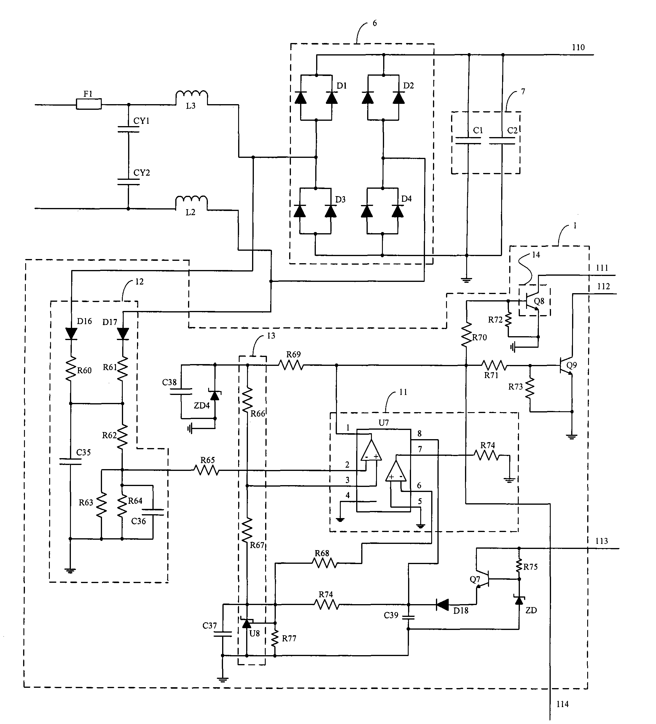
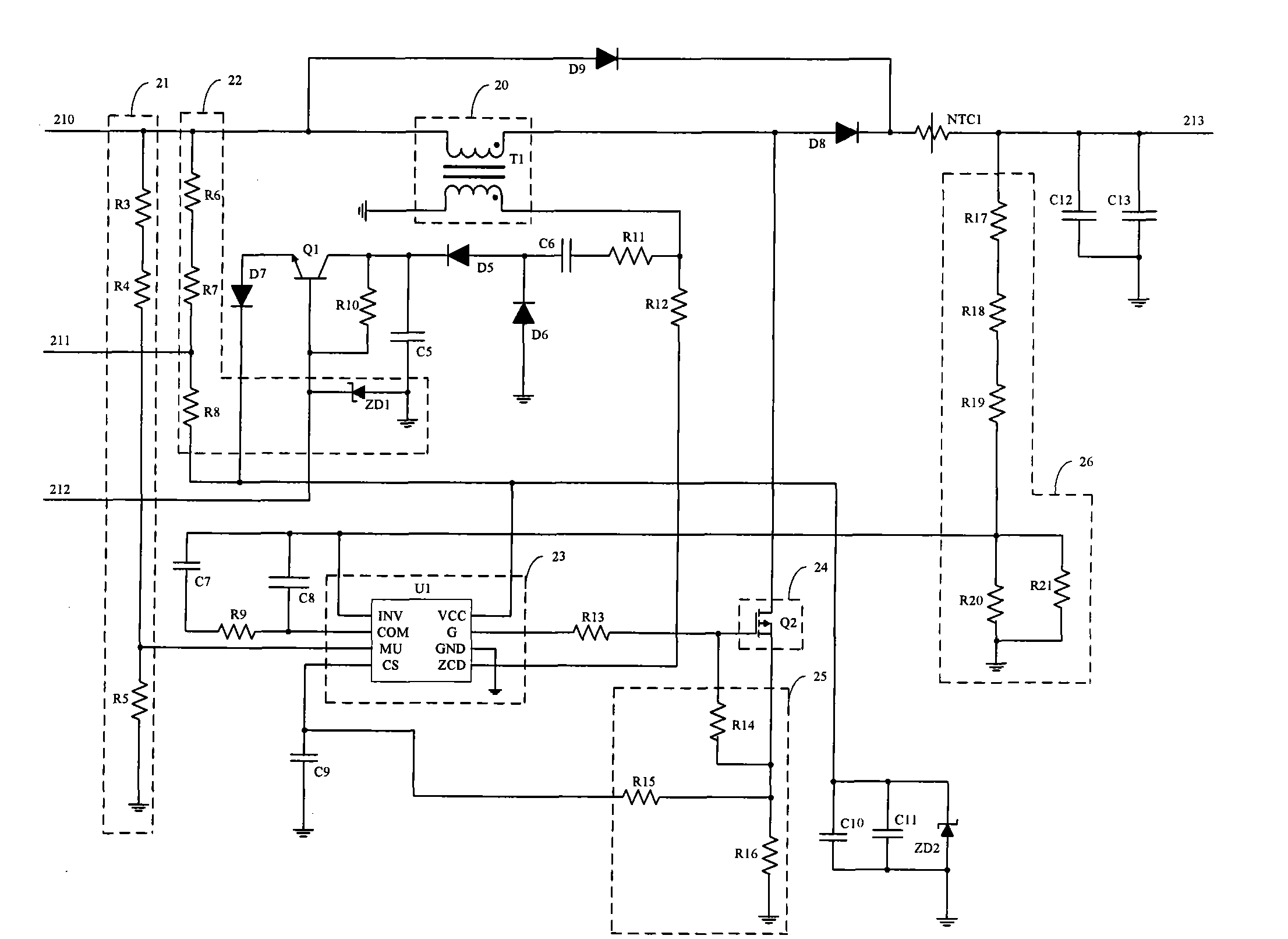
[0022] The LED control circuit includes an EMI circuit 5, a rectification circuit 6 and a filter circuit 7, an input undervoltage protection circuit 1, a PFC circuit 2, a step-down circuit 3, and an output constant current and overvoltage protection circuit 4; wherein the EMI circuit 5 and the rectification circuit 6 , the PFC ...


PUM


Abstract

The invention provides an LED control circuit, being applicable to LED field; the LED control circuit comprises an EMI circuit, a rectifier circuit, a PFC circuit and a filter circuit connected in sequence; the input end of an input undervoltage protective circuit is connected with the input end of the rectifier circuit, the first output end is connected with the control end of the PFC circuit, and the second output end is connected with the second input end of a voltage step-down circuit; the first input end of the voltage step-down circuit is connected with the output end of the filter circuit, the output end of the voltage step-down circuit is connected with the input end of an output constant current and overvoltage protective circuit; the output end of the output constant current andovervoltage protective circuit is connected with the load, and the feedback end thereof is connected with the control end of the voltage step-down circuit. The LED control circuit provided in the invention utilizes PFC circuit to lead the input power factor to be larger than 0.99 and voltage to increase to 80V simultaneously, and then utilizes the voltage step-down circuit to lead voltage to decrease to 22V, and simultaneously has the feedback circuit output constant current to ensure LED to shine constantly.

Description

technical field [0001] The invention belongs to the field of LEDs, in particular to an LED control circuit. Background technique [0002] In the existing LED control circuit, the input voltage range is relatively narrow, the input power factor is low, and the protection for the circuit board is insufficient at the same time. Contents of the invention [0003] The purpose of the embodiments of the present invention is to provide an LED control circuit, aiming at solving the problems of narrow input voltage range, low input power factor and insufficient protection function in the existing LED control circuit. [0004] The embodiment of the present invention is realized in this way. An LED control circuit includes an EMI circuit, a rectifier circuit and a filter circuit. The LED control circuit also includes: an input undervoltage protection circuit, a PFC circuit, a step-down circuit and an output constant current and an overvoltage protection circuit; the EMI circuit, the ...

Claims


Application Information

Patent Timeline
Patent Type & Authority Applications(China)
IPC IPC(8): H05B37/02F21V23/00
Inventor 周明杰陈永伦肖磊
Owner OCEANS KING LIGHTING SCI&TECH CO LTD
Learn More