
LED control system

A control system and LED light source technology, applied in the LED field, can solve the problems of low input power factor, narrow input voltage range, insufficient circuit board protection, etc., and achieve the effect of damage protection

Inactive Publication Date: 2014-08-20
ANHUI ZHAOLI OPTO ELECTRONICS TECH
View PDF0 Cites 0 Cited by
  • Summary
  • Abstract
  • Description
  • Claims
  • Application Information

AI Technical Summary

Problems solved by technology

The existing LED control circuit has a relatively narrow input voltage range, low input power factor, and insufficient protection for the circuit board

Method used


Image

  • LED control system

Examples


Embodiment Construction

[0010] The present invention will be described in detail below in conjunction with the accompanying drawings and specific embodiments.

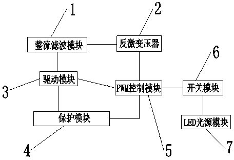
[0011] Such as figure 1 As shown, an LED control system includes a rectification and filtering module 1, a flyback transformer 2, a drive module 3, a protection module 4, a PWM control module 5 and an LED light source module 7, the input end of the rectification and filtering module 1 is connected to an alternating current, The output end is connected to the input end of the flyback transformer 2 and the drive module 3, and the output end of the flyback transformer 2 is connected to the input end of the PWM control module 5; the output end of the PWM control module 5 is connected to the drive module 3 and the drive module 3 respectively. A switch module 6, the output end of the switch module 6 is connected to the input end of the LED light source module 7, the first output end of the protection module 4 is connected to the drive module 3, and...


PUM


Abstract

Disclosed is an LED control system. The LED control system comprises a rectification filtering module, a flyback transformer, a driving module, a protection module, a PWM control module and an LED light source module. The input end of the rectification filtering module is connected with alternating currents, the output end of the rectification filtering module is connected with the input ends of the flyback transformer and the driving module, the output end of the flyback transformer is connected with the input end of the PWM control module, the output end of the PWM control module is respectively connected with the driving module and a switch module, the output end of the switch module is connected with the input end of the LED light source module, the first output end of the protection module is connected with the driving module, and the second output end of the protection module is connected with the PWM control module. The LED control system provided by the invention ensures constant luminescence of an LED and is provided with a function of protecting a circuit board from being damaged in case of a high temperature and a function of effectively protecting the LED light source module in case of circuit output abnormities.

Description

technical field [0001] The invention relates to the technical field of LEDs, in particular to an LED control system. Background technique [0002] LED lights have the advantages of high energy conversion efficiency, fast switching response, long life, no radiation, and low power consumption. They are gradually replacing most traditional lighting methods and becoming the mainstream of lighting technology development. The existing LED control circuit has relatively narrow input voltage range, low input power factor, and insufficient protection for circuit boards. Contents of the invention [0003] The object of the present invention is to provide an LED control system to solve the above problems. [0004] In order to achieve the above object, the technical scheme that the present invention takes is: [0005] An LED control system, comprising a rectification and filtering module, a flyback transformer, a drive module, a protection module, a PWM control module and an LED lig...

Claims


Application Information

Patent Timeline
Patent Type & Authority Applications(China)
IPC IPC(8): H05B37/02
Inventor 胡学军邬国平江严宝汪旭欧阳锋
Owner ANHUI ZHAOLI OPTO ELECTRONICS TECH
Learn More