A locating/guidance tip assembly for a liquid droplet spray teeth cleaning system

A technology for spraying systems and guiding components, applied in the direction of devices for cleaning dental cavities, etc., which can solve problems such as spray nozzles not being too close, damage to gums and other tissues, and efficiency decline

Active Publication Date: 2010-07-21
KONINKLIJKE PHILIPS ELECTRONICS NV
View PDF8 Cites 1 Cited by
  • Summary
  • Abstract
  • Description
  • Claims
  • Application Information

AI Technical Summary

Problems solved by technology

Spray nozzles should not be too close, which may cause damage to gums and o

Method used


Image

  • A locating/guidance tip assembly for a liquid droplet spray teeth cleaning system
  • A locating/guidance tip assembly for a liquid droplet spray teeth cleaning system
  • A locating/guidance tip assembly for a liquid droplet spray teeth cleaning system

Examples


Embodiment Construction

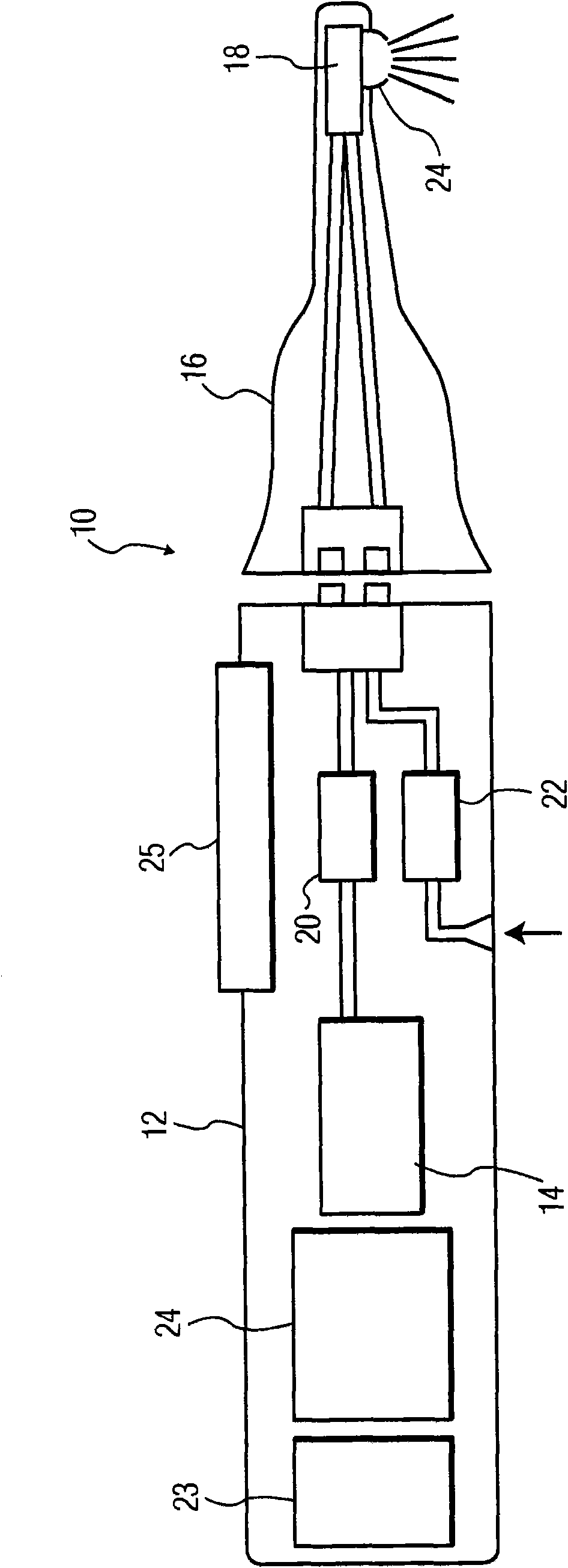
[0013] figure 1 A droplet spray dental cleaning system 10 is shown generally. A typical handheld system for home use will include a body or handle portion 12 with a liquid source 14 positioned therein. In one arrangement, gas and liquid are moved to the head 16 of the system by pumps 20-22. The liquid and gas are directed into the nebulizer assembly 18 where the gas flow creates and accelerates the droplets to the desired velocity as they exit the nozzle 24 at the end of the head to the desired location on the tooth.

[0014] In one example, the droplets range in size from 10-15 mm and are accelerated to a velocity of approximately 30 meters per second. However, other arrangements with different sized droplets and different velocities may be used, eg a maximum velocity of 70 meters per second. In this embodiment, the head 16 is arranged to be replaceable with respect to the handle portion which includes the liquid and gas supply, the electronic control 24 and the system pow...


PUM


Abstract

The spray assembly for a droplet spray teeth cleaning system includes a guidance member (40, 56, 80, 86) at the end thereof. The spray assembly includes a nozzle (24) through which a spray of liquid is directed to the teeth for cleaning. The guidance member is configured and mounted relative to the nozzle to provide a selected standoff distance between the nozzle and the teeth and includes a portion which is configured to fit in the interproximal space between adjacent teeth and gums, or against the frontal portions of the teeth, so that the user knows the location of the spray relative to the teeth.

Description

technical field [0001] The present invention relates generally to droplet spray dental cleaning systems, and more particularly to a droplet spray portion of a dental cleaning system that includes a guide tip for properly positioning a droplet sprayer relative to teeth. Background technique [0002] Droplet spray dental cleaning systems are well known and various droplet spray systems are described in various patents and published patent publications. One such patent publication is WO200507034, owned by the assignee of the present invention, the content of which is hereby incorporated by reference. In this application, liquid droplets (water droplets) are generated and then accelerated to a desired velocity by a gas flow such as air. In other systems, other means are used, such as swirl nozzles using high pressure, to accelerate the droplets to the desired velocity. The droplets must be of a specific size and velocity in order to have an effective cleaning effect on the tee...

Claims


Application Information

Patent Timeline
IPC IPC(8): A61C17/02
CPCA61C17/0202A61C17/0217
Inventor G·科特拉奇克J·格雷兹C·布莱克B·J·马西P·巴斯P·A·瓦赫特斯K·罗基特W·本宁J·伍德P·C·杜因维尔德J·J·M·詹森P·D·利尤乌P·d·利尤乌
Owner KONINKLIJKE PHILIPS ELECTRONICS NV
Why Eureka
Try Eureka