
Device and method for interproximal reduction

a technology of interproximal reduction and device, applied in the field of dental surgery, can solve the problems of difficulty in reducing affecting the correct amount of tooth, and moving or moving teeth,

Inactive Publication Date: 2019-12-12
LOPEZ BRENT K
View PDF0 Cites 1 Cited by
  • Summary
  • Abstract
  • Description
  • Claims
  • Application Information

AI Technical Summary

Benefits of technology

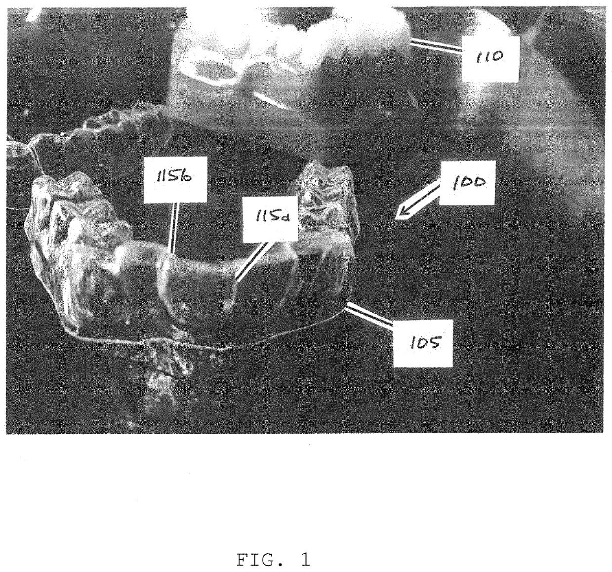
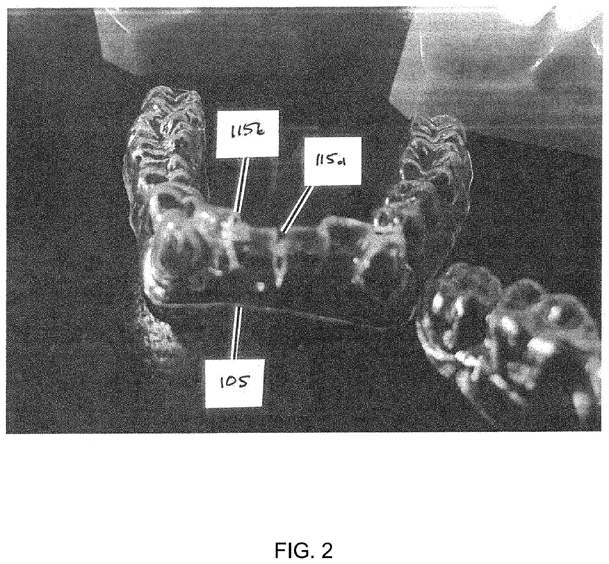
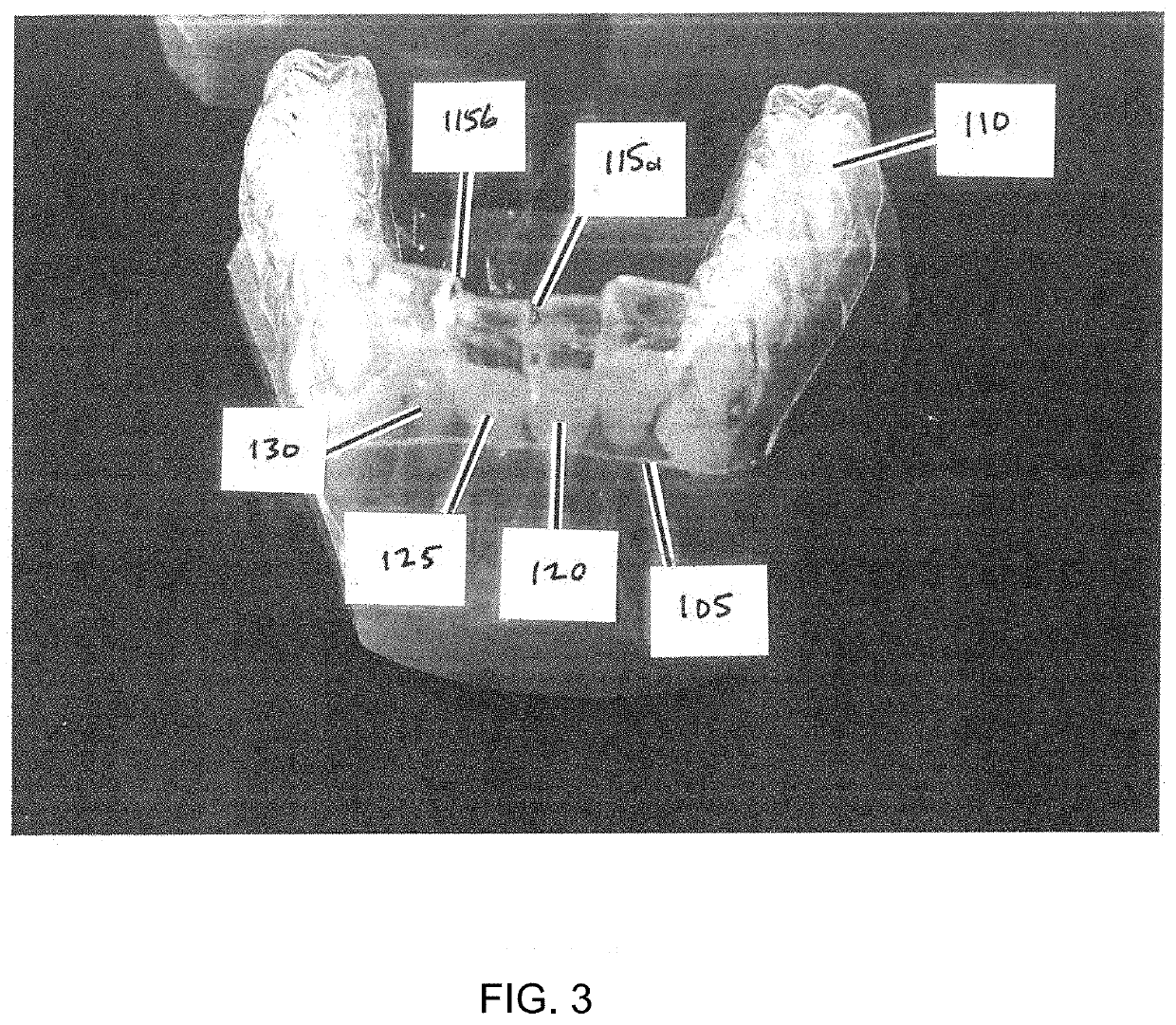
The patent describes a guide for dental interproximal reduction that includes a tray shaped to hold teeth stationary during the reduction. The tray has grooves that allow an instrument to access the space between teeth for reduction. The guide also includes a first and second lateral edge in each groove to guide the instrument for interproximal reduction. The guide can be made from materials such as polyetherurethane, polycarbonate, and other materials that abrade tooth enamel. The instrument can include a reducing edge or surface made of materials such as diamond, metal, silicates, or other materials that abrade tooth enamel. The technical effects of the patent include improved precision and control during dental interproximal reduction procedures.

Problems solved by technology

A practitioner performing an interproximal reduction or an interproximal dental enameloplasty may encounter a number of difficulties.
These possible difficulties include a moving or mobile tooth, difficulty in reducing the correct amount of tooth, and inadvertently reducing a tooth such that a ledge or notch is created (“ledging”).
Precision in interproximal reduction is difficult to achieve when this is the case.
It is also difficult to remove the correct amount of tooth, given the small amounts at issue and the limitations inherent in manually manipulating an interproximal reduction instrument.
Inadvertent creation of a ledge or notch is a specific difficulty of removing the correct amount, as when too much tooth is removed in a small part of the larger tooth portion to be reduced or when, while reducing one tooth, the interproximal reduction instrument touches the adjacent tooth across the interproximal space.
Existing devices and methods for interproximal reduction are inadequate to prevent or reduce the difficulties in performing the procedure.

Method used


Image

  • Device and method for interproximal reduction
  • Device and method for interproximal reduction
  • Device and method for interproximal reduction

Examples


Embodiment Construction

[0028]Illustrative embodiments of the system of the present application are described below. In the interest of clarity, not all features of an actual implementation are described in this specification. It will of course be appreciated that in the development of any such actual embodiment, numerous implementation-specific decisions must be made to achieve the developer's specific goals, such as compliance with system-related and business-related constraints, which will vary from one implementation to another. Moreover, it will be appreciated that such a development effort might be complex and time-consuming but would nevertheless be a routine undertaking for those of ordinary skill in the art having the benefit of this disclosure.

[0029]In the specification, reference may be made to the spatial relationships between various components and to the spatial orientation of various aspects of components as the devices are depicted in the attached drawings. However, as will be recognized by...


PUM


Abstract

A guide for dental interproximal reduction, the guide including a tray shaped to substantially conform to one or more teeth, wherein the tray holds at least one of the one or more teeth stationary during the interproximal reduction; one or more grooves in the tray, each groove positioned to allow access to an interproximal space between a first tooth and a second tooth; and a first lateral edge in each of the one or more grooves, wherein the first lateral edge is shaped to guide an instrument for interproximal reduction of the first tooth.

Description

CROSS-REFERENCE TO RELATED APPLICATIONS[0001]This patent application claims priority to U.S. provisional patent application Ser. No. 62 / 681,787 filed on Jun. 7, 2018 entitled “DEVICE AND METHOD FOR INTERPROXIMAL REDUCTION,” all of which is hereby incorporated by reference in its entirety.STATEMENT OF FEDERALLY FUNDED RESEARCH[0002]Not applicable.TECHNICAL FIELD OF THE INVENTION[0003]The present invention relates in general to the field of dental surgery. In particular, the present invention relates to interproximal reduction.BACKGROUND OF THE INVENTION[0004]Without limiting the scope of the invention, its background is described in connection with orthodontic interproximal reduction.[0005]One patent, U.S. Pat. No. 9,504,533, issued to Groscurth et al., is said to disclose a dental surgical drill guide assembly and method including a surgical guide housing and a base frame that fits to both gum tissue and one or multiple small areas of jawbone. The apparatus may be configured to accu...

Claims


Application Information

Patent Timeline
Patent Type & Authority Applications(United States)
IPC IPC(8): A61C1/08
CPCA61B2034/105A61C1/082A61B2034/108
Inventor LOPEZ, BRENT K.
Owner LOPEZ BRENT K
Learn More