Car-following synchronous side-tipping grain conveying device of corn ears

A technology of corn ears and conveying devices, which is applied in the direction of agricultural machinery and implements, applications, harvesters, etc., can solve the problems of long vehicle body, unsatisfactory harvesting efficiency, and limited use, so as to reduce the number of times of unloading grain and save unloading costs. Grain time, the effect of improving harvesting efficiency

Inactive Publication Date: 2011-08-17
LUOYANG ZHONGSHOU MACHINERY & EQUIP
View PDF0 Cites 0 Cited by
  • Summary
  • Abstract
  • Description
  • Claims
  • Application Information

AI Technical Summary

Problems solved by technology

[0002] At present, corn combine harvesters at home and abroad generally use the ear elevator to directly transport the harvested ears to the grain box. In this way, the harvesting time and grain unloading time of the corn combine harvester are almost equal, so the designer has to adopt The method of large grain box enables users to reduce the number of unloading grains and unloading time to improve harvesting efficiency, but this method of improving harvesting efficiency is not ideal, and it has become a bottleneck in the development of corn combined harvesting machinery in my country
The grain unloading device used by the Ukrainian K6 corn combine harvester is a trailer that is hung behind the combine harvester. Although the effect is good, its length is only suitable for large farms, and there are still many small and medium-sized plots in our country that are limited in use.

Method used


Image

  • Car-following synchronous side-tipping grain conveying device of corn ears
  • Car-following synchronous side-tipping grain conveying device of corn ears
  • Car-following synchronous side-tipping grain conveying device of corn ears

Examples


Embodiment Construction

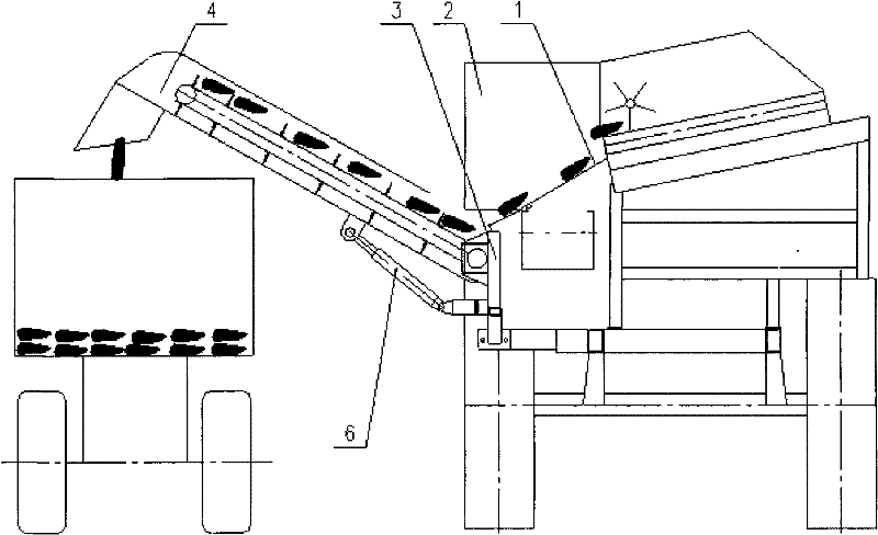
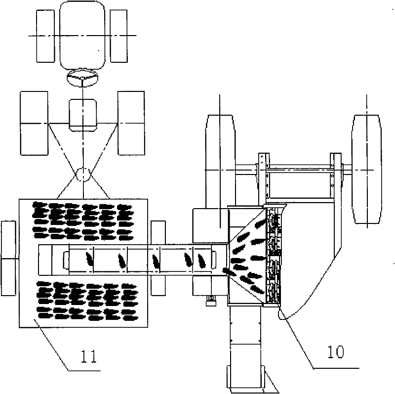
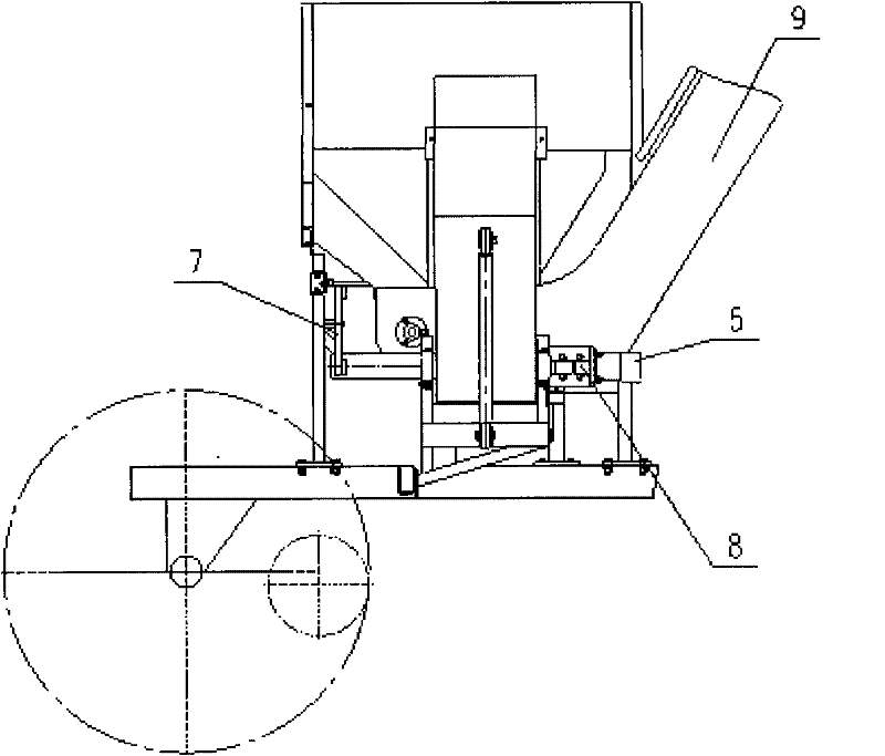
[0013] Such as Figure 1-Figure 3 As shown, the synchronous side unloading conveying device for corn ears following the car is mainly composed of the ear distribution lower plate 1, the scion groove 2, the secondary elevator bracket 3, the ear lateral conveyor 4, the hydraulic drive 5, the oil cylinder 6, and the connecting rod 7 , universal joint 8, and secondary elevator 9, the ear lateral conveyor 4 is installed in the "U"-shaped seat of the secondary elevator bracket 3, and one end of the oil cylinder 6 is installed on the ear lateral conveyor 4 On the support, the other end is installed on the support of the secondary elevator bracket 3, the scion groove 2 is installed on the horizontal section of the secondary elevator 9, and the ear distribution lower plate 1 is installed on the secondary elevator 9 In the horizontal section sleeve pipe, one end of the connecting rod 7 is connected with the upper rotating shaft support arm of the fruit ear distribution lower plate 1, an...


PUM


Abstract

The invention relates to a car-following synchronous side-tipping grain conveying device of corn ears, which mainly comprises a lower ear distribution sliding plate, an ear receiving groove, a secondary lift conveyer bracket, an ear side conveyer, a hydraulic driver, an oil cylinder, a connecting rod, a cardan joint and a secondary lift conveyer. The ear side conveyer is installed in a U-shaped seat of the secondary lift conveyer bracket, the oil cylinder is installed on the ear side conveyer and a supporting seat of the secondary lift conveyer bracket, the ear receiving groove is installed at a horizontal section of the secondary lift conveyer, and the lower ear distribution sliding plate is installed in a sleeve at the horizontal section of the secondary lift conveyer and carries out a reverse fan-shaped motion by taking the sleeve as an axis through the connecting rod along with the motion change of the ear side conveyer. When the travel change of the ear side conveyer along with the oil cylinder is shortest, one end of the lower ear distribution sliding plate is positioned at the ear outlet end of a peeler which is transversely arranged, and the hydraulic driver is connected with a driving shaft of the ear side conveyer by the cardan joint and drives the ear side conveyer to convey the corn ears sliding down from the lower ear distribution sliding plate and the ear receiving groove onto a synchronous transporter, thereby realizing car-following synchronous grain tipping.

Description

technical field [0001] The invention belongs to the field of harvesting machinery, and in particular relates to a side unloading conveying device for corn ears synchronously following a vehicle. Background technique [0002] At present, corn combine harvesters at home and abroad generally use the ear elevator to directly transport the harvested ears to the grain box. In this way, the harvesting time and grain unloading time of the corn combine harvester are almost equal, so the designer has to adopt The method of large grain box allows users to reduce the number of unloading grains and unloading time to improve harvesting efficiency, but this method of improving harvesting efficiency is not ideal, and has become a bottleneck in the development of corn combined harvesting machinery in my country. The grain unloading device used by the Ukrainian K6 corn combine harvester is a trailer that is hung behind the combine harvester. Although the effect is good, its length is only suit...

Claims


Application Information

Patent Timeline
Patent Type & Authority Patents(China)
IPC IPC(8): A01D45/02
Inventor 李晓华高海涛宋伟航冯小川刘永福徐锋毛珠雄
Owner LUOYANG ZHONGSHOU MACHINERY & EQUIP
Why Eureka
Try Eureka