Harvester grain bin

A technology for harvesters and granaries, applied to harvesters, cutters, agricultural machinery and implements, etc., can solve problems such as low work efficiency, long unloading time, and increased number of unloading times, so as to improve work efficiency and evenly distribute grain , The effect of reducing the number of unloading grain

Active Publication Date: 2016-03-23
JIANGSU WORLD AGRI MACHINERY
View PDF8 Cites 1 Cited by
  • Summary
  • Abstract
  • Description
  • Claims
  • Application Information

AI Technical Summary

Problems solved by technology

[0002] At present, the granary of the vertical axis flow wheel harvester is a tipping bucket type. Since the middle of the granary is high and the sides are low, and the position of the grain outlet of the granary is relatively low, this causes the grain to accumulate or even block the grain at the grain outlet on one side of the granary. At the same time, there is little grain on the other side of the granary, and the grain must be unloaded at this time, resulting in uneven distribution of grain in the granary, low grain collection rate, and increased unloading times
In addition, when unloading grain, the grain slides down along the grain unloading plate as the granary rises. Since the height of the grain unloading plate from the ground is too low, the grain cannot be unloaded directly on the grain truck. It takes a long time to unload the grain to re-collect the grain on the grain truck, the operation is cumbersome, time-consuming and labor-intensive, and the work efficiency is low

Method used


Image

  • Harvester grain bin
  • Harvester grain bin
  • Harvester grain bin

Examples


Embodiment Construction

[0017] The present invention will be further described below in conjunction with drawings and embodiments.

[0018] In the present invention, the running direction of the harvester is the front, and vice versa.

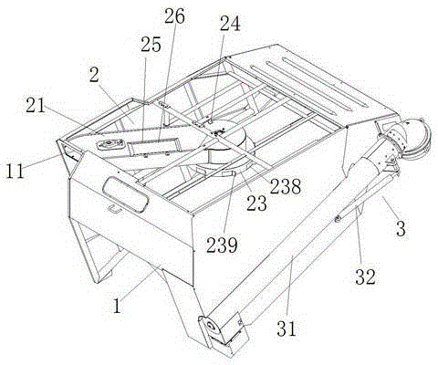
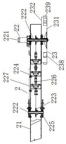
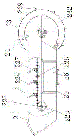
[0019] like figure 1 , figure 2 , image 3 and Figure 4 As shown, the present invention includes a bin body 1, a transition conveying mechanism 2 and an overhanging grain unloading mechanism 3. The transition conveying mechanism 2 is longitudinally arranged in the bin body 1 and is located inside the grain inlet 11 of the bin body 1 . The front end of the transition conveying trough 21 is fixedly connected with the grain inlet 11 of the silo body through bolts, and the upper side of the rear end is fixedly connected with the top of the silo body 1 through the connecting seat 24. The top side of the transition conveying trough 21 is provided with an inspection port 25 and an inspection cover 26 Cover on the inspection port 25.

[0020] The conveying driving uni...


PUM


Abstract

The invention discloses a harvester grain bin. The harvester grain bin comprises a bin body, a transitional conveying mechanism and an externally-extending unloading mechanism; the transitional conveying mechanism is longitudinally arranged in the bin body and comprises a transitional conveying groove, a conveying driving unit and a projecting disc; the conveying driving unit is arranged in the transitional conveying groove and comprises a hydraulic motor, two transmission shafts, a pair of chain wheels and a plurality of scraper plates; the projecting disc is fixedly installed at the lower end of one of the transmission shafts in a sleeving mode, a projecting disc body comprises an inner spreading plate and an outer projecting plate, the disc body is divided into an inner ring area and an outer ring area by the inner spreading plate, multiple spreading openings are evenly formed in the outer circumference of the inner spreading plate, and multiple grain throwing openings are evenly formed in the outer circumference of the outer projecting plate; the externally-extending unloading mechanism is arranged at one side of the bin body. By means of the harvester grain bin, it is guaranteed that grains in the bin body of the grain bin can be distributed uniformly, the grain collection rate of the grain bin is greatly raised, meanwhile, grain discharging times are decreased, and work efficiency is improved. When the bin body of the grain bin is filled up with the grains, the grains can be directly unloaded onto a grain transporting vehicle, time and labor are saved, and grain unloading time is saved.

Description

technical field [0001] The invention relates to a harvester grain collecting device, in particular to a harvester granary with a high grain collection rate, belonging to the technical field of agricultural machinery. Background technique [0002] At present, the granary of the vertical axis flow wheel harvester is a tipping bucket type. Since the middle of the granary is high and the sides are low, and the position of the grain outlet of the granary is relatively low, this causes the grain to accumulate or even block the grain at the grain outlet on one side of the granary. At the same time, there is a phenomenon that there is little grain on the other side of the granary, and the grain must be unloaded at this time, resulting in uneven distribution of grain in the granary, low grain collection rate, and increased unloading times. In addition, when unloading grain, the grain slides down along the grain unloading plate as the granary rises. Since the height of the grain unloa...

Claims


Application Information

Patent Timeline
Patent Type & Authority Applications(China)
IPC IPC(8): A01D43/063
CPCA01D43/063
Inventor 张艺辉王炜
Owner JIANGSU WORLD AGRI MACHINERY
Why Eureka
Try Eureka