Locking device

A locking device and locking pin technology, which are applied in building locks, electric alarm locks, connecting components, etc., can solve the problem of high cost of the lock tongue accommodating part

Active Publication Date: 2010-08-11
PILZ AUSLANDSBETEILIGUNGEN
View PDF7 Cites 2 Cited by
  • Summary
  • Abstract
  • Description
  • Claims
  • Application Information

AI Technical Summary

Problems solved by technology

The bolt receptacle is structurally complex and ad...

Method used


Image

  • Locking device
  • Locking device
  • Locking device

Examples


Embodiment Construction

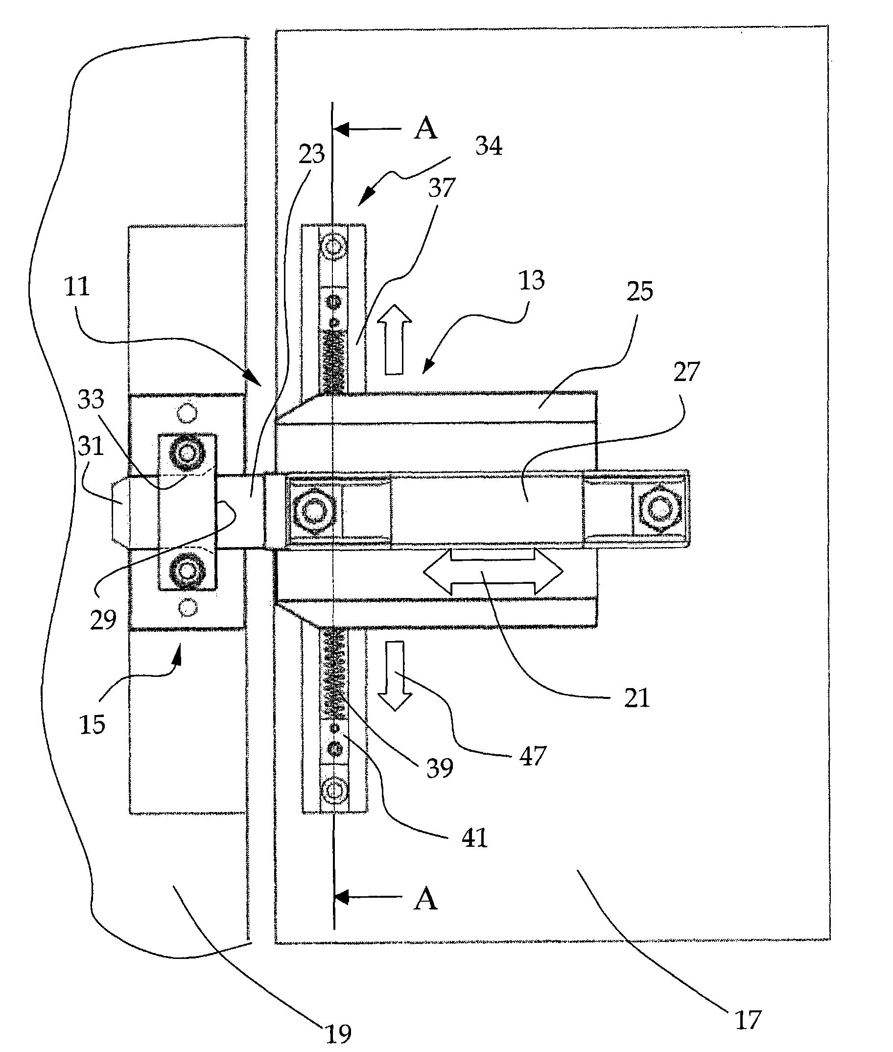
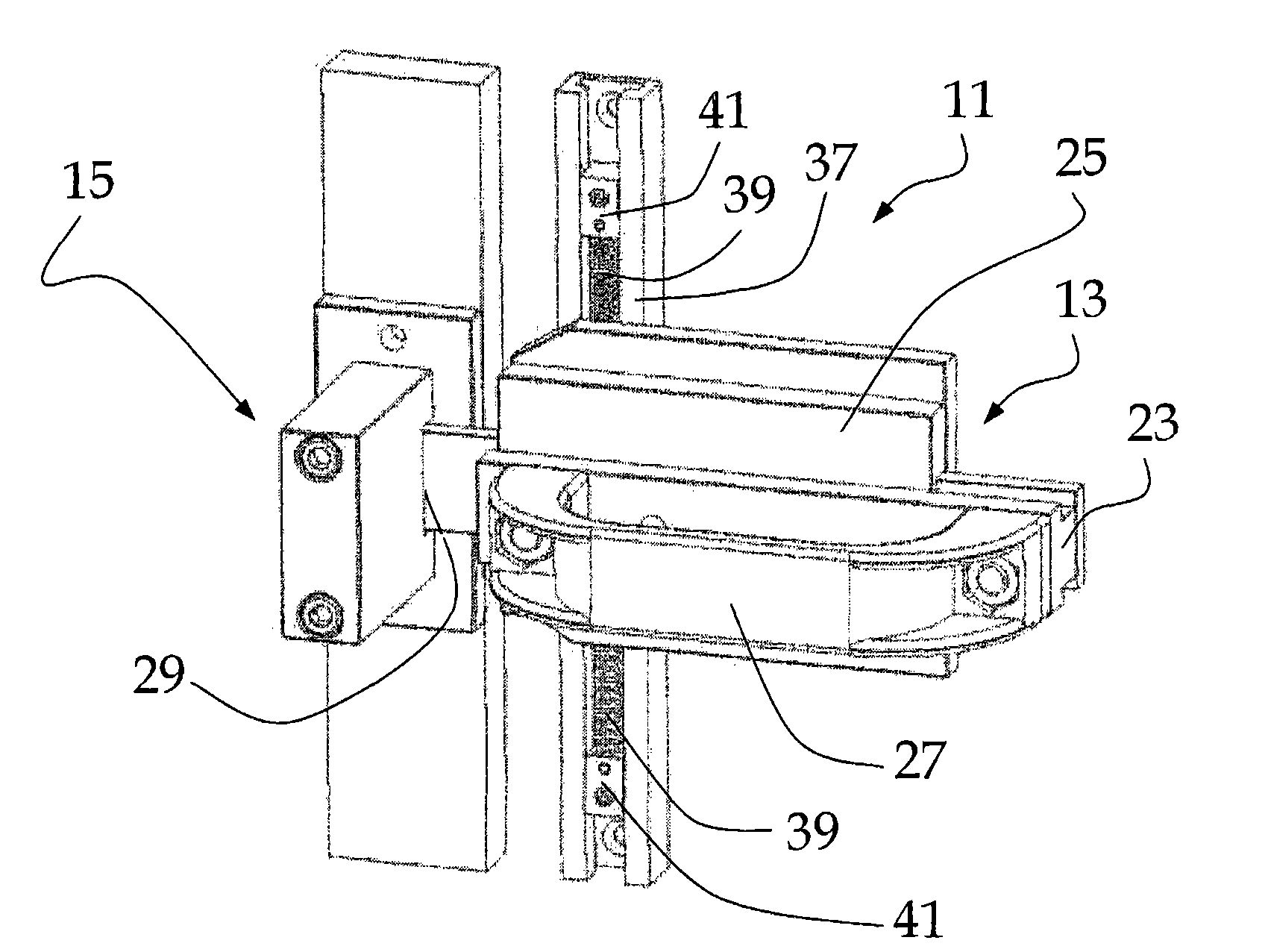
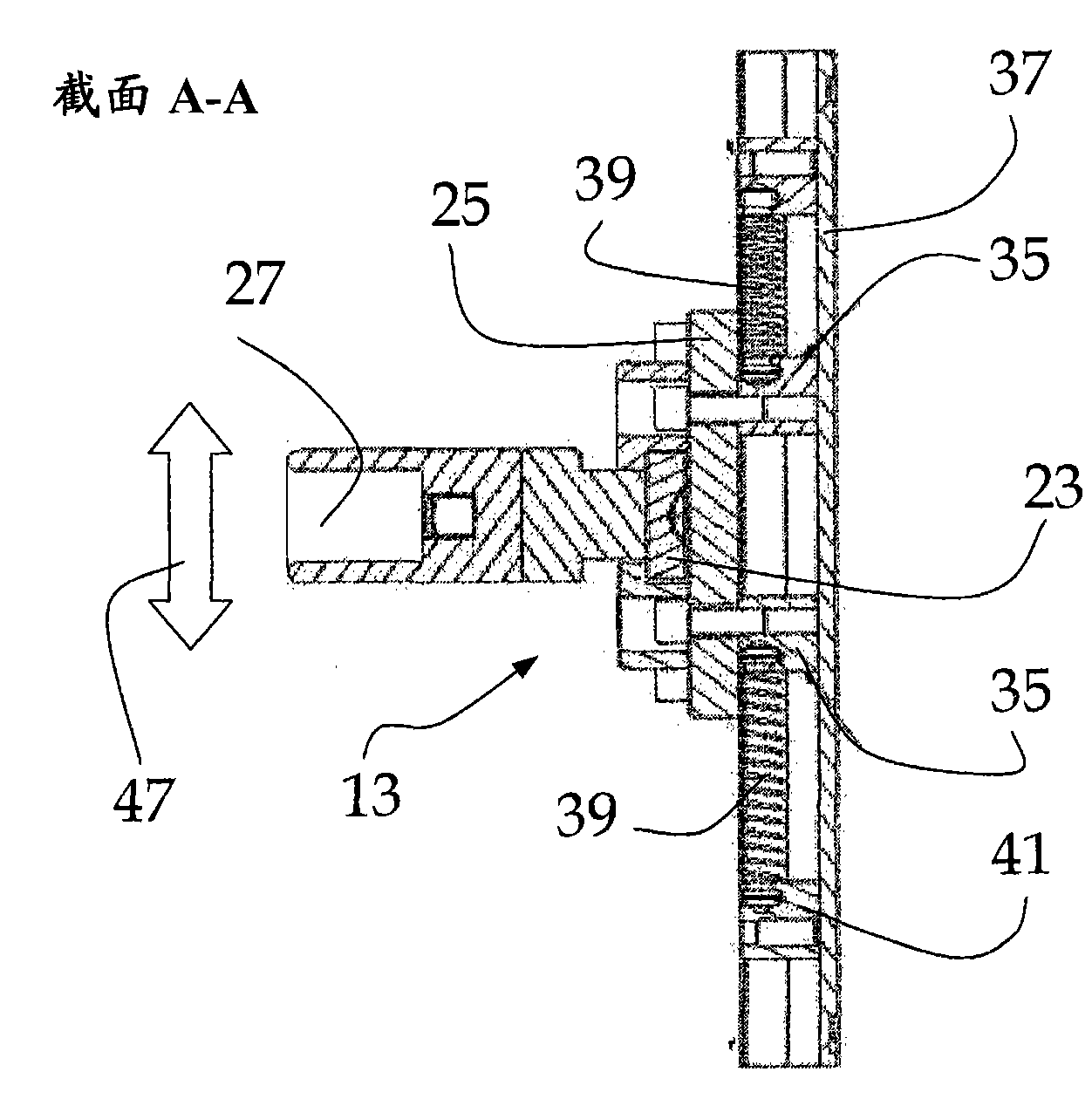
[0052] Figure 1 to Figure 3 A locking device 11 is shown with a latch part 13 and a latch part 15 . From figure 1 As can be seen in , the latch part 13 is positioned at the door 17 and the latch part 15 is positioned at the space divider 19 . The locking pin part comprises a locking pin 23 movable in the longitudinal direction of movement 21 . The longitudinal guide 25 acts on the locking pin 23 as guide and retainer during the movement of the locking pin 23 in the longitudinal displacement direction 21 . A handle 27 is arranged on the locking pin 23 . The latch part 15 has a receiving opening 29 . In order to accommodate the locking pin 23 easily in the receiving opening 29 , there is a chamfer 31 at the end of the locking pin 23 facing the receiving opening 29 . The receiving opening 29 is likewise rounded by a chamfer 33 . Such as image 3 Available in , the latch part 13 has a lateral guide 34 . The transverse guide 34 comprises two sliding bodies 35 and a guide r...


PUM


Abstract

The present invention relates to a locking device (11); the locking device (11) is provided with a bolt part (13) and a lock part (15) being used for a door arranged at a space separator part having an opening and a closing opening. The bolt part (13) is provided with a longitudinal guiding device (25) and a bolt (23) which moves on a longitudinal movement direction corresponding to the longitudinal guiding device (25). The lock part (15) is provided with a containing opening (29) which is used for containing a first end of the bolt (23). The bolt part (13) is further provided with a transverse guiding device except from the longitudinal guiding device (25). A spiral spring (39) is in active engagement with the longitudinal guiding device (25) and the transverse guiding device to cushion the movement of the bolt (23) of the bolt (23) in a transverse adjustment direction (47). The adjustment direction (47) is directed by means of vertical to the movement direction (21) of the bolt (23)and parallel to the door plane, and is defined by the transverse guiding device.

Description

technical field [0001] The invention relates to a locking device (Verriegelungseinrichtung) according to the preamble of claim 1 , and to a room divider (Raumabschluss) with such a locking device according to the preamble of claim 13 . Background technique [0002] Doors and gates are mostly locked using a lock and pin (Riegel) system. Very heavy doors and gates are prone to: not snapping into the door frame or gate frame with an exact fit, or deviating from their original fit accuracy over time. Also a consequence of this inaccuracy in the fit between the door and the frame is that the doors and gates can no longer be locked with the system of the catch and the deadbolt; the deadbolt can no longer move into in the lock. This precision of fit can be compensated for by a simple constructional measure, namely widening the locking pin receptacle of the locking opening and thus increasing the play of the locking pin in the locking opening. The disadvantage of this simple cont...

Claims


Application Information

Patent Timeline
IPC IPC(8): E05B63/08E05B15/10E05B15/04E05B45/06
CPCE05B15/024E05B15/02E05C1/04E05B45/06E05B15/022E05B63/0056Y10T70/5155Y10T292/096Y10T292/0969Y10T292/102
Inventor F·马迪
Owner PILZ AUSLANDSBETEILIGUNGEN
Why Eureka
Try Eureka