
Monitoring of condensate drains

A technology of condensate and excretor, which is applied to steam/steam condensers, instruments, steam traps, etc., and can solve the problems of not being able to get the working status and not being able to accurately determine it

Active Publication Date: 2018-03-16
GESTRA AKTIENGES
View PDF5 Cites 0 Cited by
  • Summary
  • Abstract
  • Description
  • Claims
  • Application Information

AI Technical Summary

Problems solved by technology

[0008] By evaluating the sound intensity in the ultrasonic range only, it cannot be determined exactly whether the condensate drain is just draining or has steam breakthrough due to damage
In this case, no clear determination of the status of the work will be drawn

Method used


Image

  • Monitoring of condensate drains
  • Monitoring of condensate drains
  • Monitoring of condensate drains

Examples


Embodiment Construction

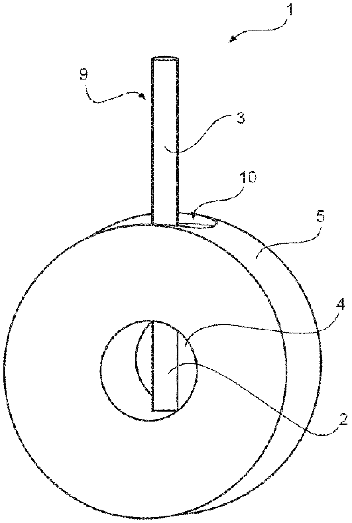
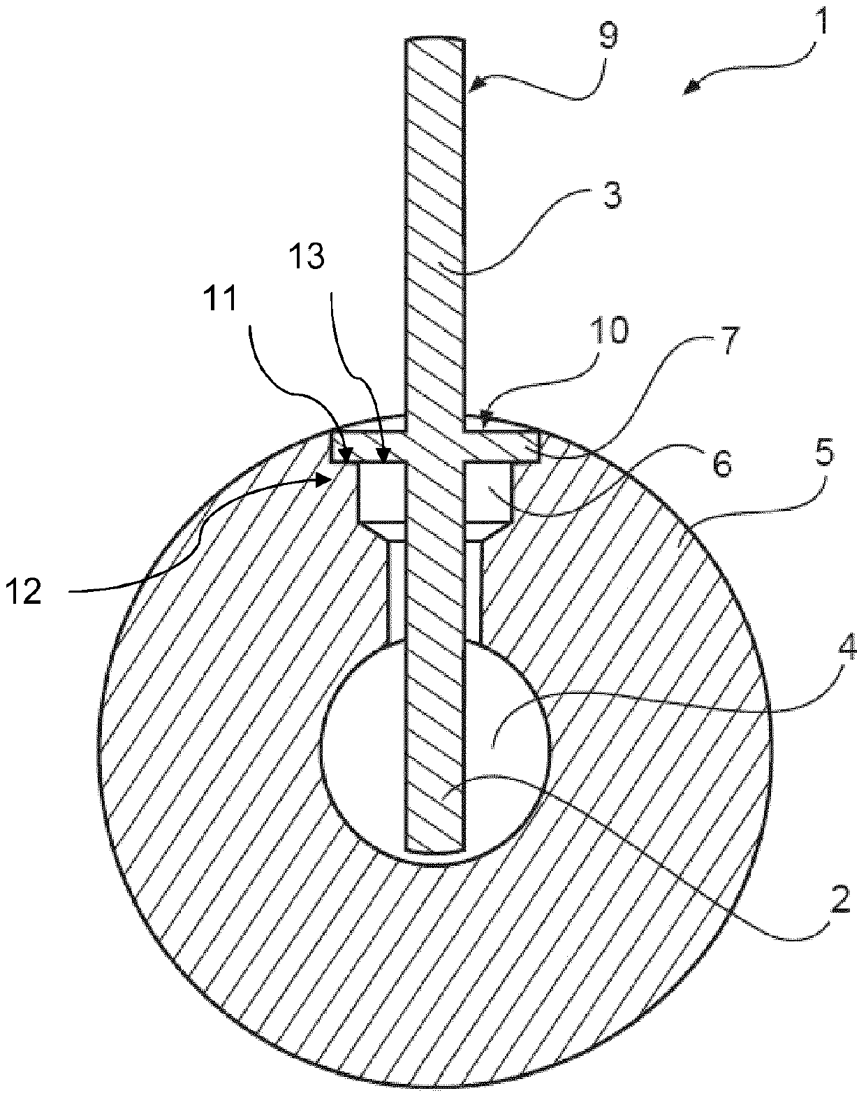
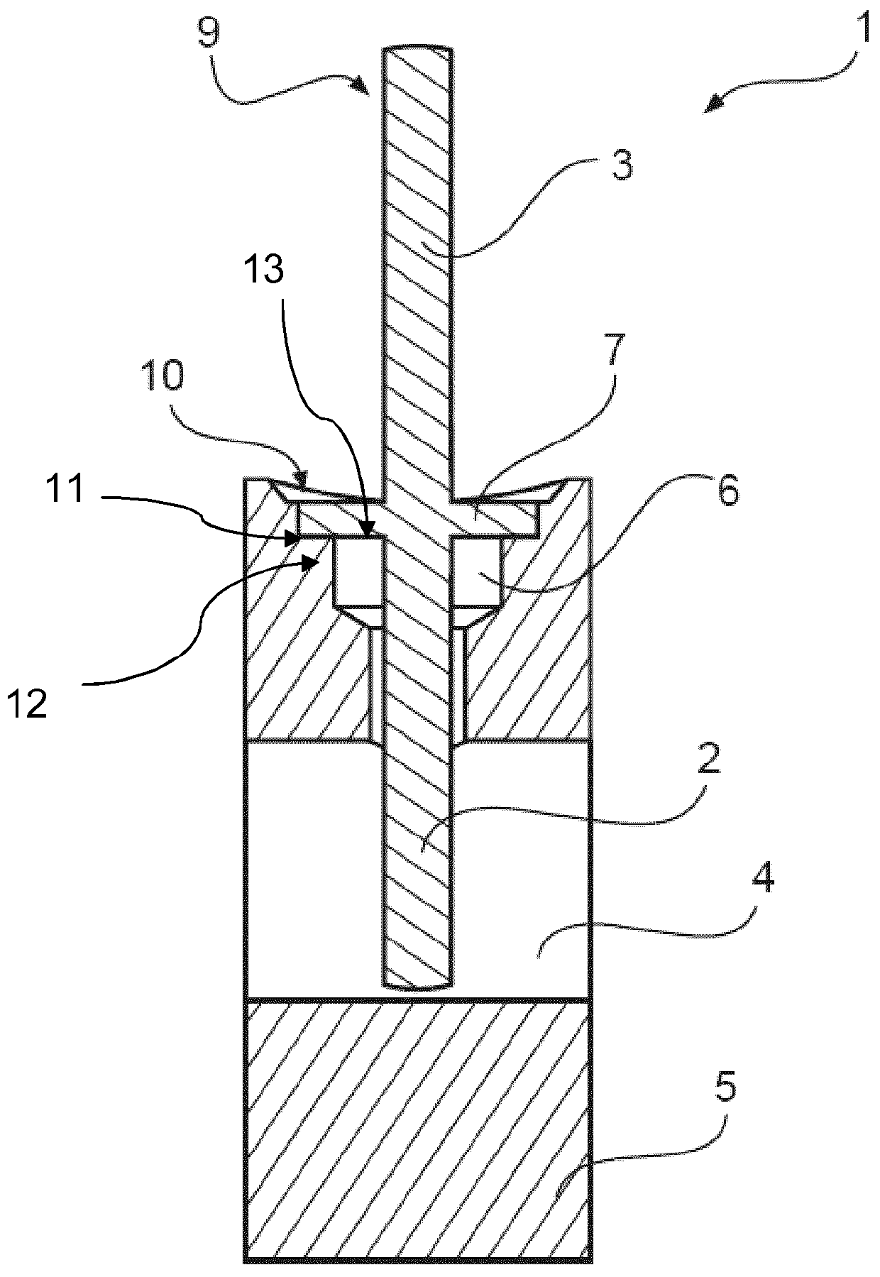
[0059] figure 1 Shown is flow sensor 1 with vibrating body 9 and base body 5 , which is designed in the form of a ring. The vibrating body 9 is designed here in the form of a rod and has a first region 2 and a second region 3 . An opening 10 is provided in the base body 5 , in which opening the vibrating body 9 is arranged. The basic body 5 has an opening 4 with a predetermined flow cross section. The first region 2 of the vibrating body 9 protrudes into the opening 4. Alternatively, the vibrating body 9 can be designed such that the first region adjoins the flow cross section for the medium, ie is arranged adjacent to the flow cross section and thus at least partially contacts the flow surface. A medium, such as a multiphase flow, such as steam and condensate, flows through the predetermined cross section 4 . The second region 3 protrudes from the base body 5 above the opening 10 .

[0060] figure 2 and image 3 A cross section of the flow sensor 1 is shown. right f...


PUM


Abstract

The invention relates to a flow sensor and a method for monitoring a condensate drain (20), said method comprising the following steps: a) providing a flow sensor (1) to detect media-carrying pipes and / or fittings The flow characteristics in; b) detect the vibration performance by means of the vibration transducer (112) on the measurement site (8) arranged on the flow sensor (1); c) electronically carry out the vibration performance of the vibration body (9) Evaluation in which the vibrations of a first area (2) of the vibrating body (9) at least partially arranged in or near the medium flow and the arrangement of the vibrating body (9) outside the flow are recorded at the measuring point (8) The vibration of the second zone (3).

Description

technical field [0001] The invention relates to a method for monitoring a condensate drain, a flow sensor for detecting the flow properties of a pipe and / or a fitting carrying a medium, in particular a condensate drain, and a method for monitoring at least A monitoring device for the condensate drain. Background technique [0002] Condensate drains are commonly used in facilities in the chemical industry, the pharmaceutical industry and the energy technology industry to drain condensate formed in steam lines or vessels or molding processes from the facility. In this case, the draining of the condensate must take place at a certain point in time in order to prevent a so-called water surge and for efficient energy use. This water impingement occurs when steam is introduced into or occurs in a liquid having a lower temperature. Furthermore, the condensate drain should prevent the escape of steam in the absence of condensate. [0003] In such installations, wear phenomena, co...

Claims


Application Information

Patent Timeline
Patent Type & Authority Patents(China)
IPC IPC(8): F16T1/48F16T1/00G01P5/24G01F1/28F28B11/00G01F1/32G01F23/296
CPCF28B11/00G01P5/24G01F1/00G01F1/28F28F17/005F28B9/08F28F2265/00F16T1/48G01N29/032G01N29/36
Inventor 谢尔盖·扬森霍尔格·施勒特尔于尔根·克拉滕霍夫
Owner GESTRA AKTIENGES
Learn More